Product Description
Professional CNC Machining Parts Supplier-HangZhou XINGXIHU (WEST LAKE) DIS.NG PRECISION INDUSTRY CO.,LTD.-Focus on & Professional
| Material: | Aluminum (6061-T6, 6063, 7075-T6,5052) etc… |
| Brass/Copper/Bronze etc… | |
| Stainless Steel (201, 302, 303, 304, 316, 420, 430) etc… | |
| Steel (mild steel, Q235, 20#, 45#) etc… | |
| Plastic (ABS, Delrin, PP, PE, PC, Acrylic) etc… | |
| Process: | CNC Machining, turning,milling, lathe machining, boring, grinding, drilling etc… |
| Surface treatment: | Clear/color anodized; Hard anodized; Powder-coating;Sand-blasting; Painting; |
| Nickel plating; Chrome plating; Zinc plating; Silver/gold plating; | |
| Black oxide coating, Polishing etc… | |
| Gerenal Tolerance:(+/-mm) | CNC Machining: 0.005 |
| Turning: 0.005 | |
| Grinding(Flatness/in2): 0.005 | |
| ID/OD Grinding: 0.002 | |
| Wire-Cutting: 0.003 | |
| Certification: | ISO9001:2008 |
| Experience: | 15 years of CNC machining products |
| Packaging : | Standard: carton with plastic bag protecting |
| For large quantity: pallet or as required | |
| Lead time : | In general:15-30days |
| Term of Payment: | T/T, Paypal, Western Union, L/C, etc |
| Minimum Order: | Comply with customer’s demand |
| Delivery way: | Express(DHL,Fedex, UPS,TNT,EMS), By Sea, By air, or as required |
/* January 22, 2571 19:08:37 */!function(){function s(e,r){var a,o={};try{e&&e.split(“,”).forEach(function(e,t){e&&(a=e.match(/(.*?):(.*)$/))&&1
| Application: | Auto and Motorcycle Accessory, Machinery Accessory |
|---|---|
| Standard: | GB, EN, API650, China GB Code, JIS Code, TEMA, ASME |
| Surface Treatment: | Polishing |
| Production Type: | Mass Production |
| Machining Method: | CNC Machining |
| Material: | Steel, Brass, Alloy, Copper, Aluminum, Iron |
| Samples: |
US$ 1/Piece
1 Piece(Min.Order) | |
|---|
| Customization: |
Available
| Customized Request |
|---|

How do PTO drive shafts handle variations in length and connection methods?
PTO (Power Take-Off) drive shafts are designed to handle variations in length and connection methods, allowing them to be adaptable to different equipment setups and applications. These variations are accommodated through the following features and mechanisms:
1. Telescoping Design:
Many PTO drive shafts are designed with a telescoping mechanism, which enables the length of the drive shaft to be adjusted. Telescoping allows for flexibility in matching the distance between the power source (e.g., tractor PTO) and the driven equipment. By extending or retracting the telescoping sections of the drive shaft, operators can achieve the desired length and ensure proper alignment. This feature is particularly useful when connecting equipment that may have varying distances from the power source.
2. Overlapping Tubes:
PTO drive shafts often consist of multiple tubes that overlap when the drive shaft is fully collapsed. These overlapping tubes provide structural stability and allow for the length adjustment of the drive shaft. By extending or retracting the drive shaft, the overlapping tubes slide within each other, accommodating variations in length. The overlapping tube design ensures that the drive shaft maintains its integrity and alignment during operation.
3. Splined Connections:
PTO drive shafts typically feature splined connections, which provide a secure and reliable method of joining the drive shaft components. Splines are ridges or teeth machined onto the drive shaft and mating component, such as the yoke or flange. The splined connections allow for angular misalignment and axial movement while transmitting power smoothly. They can accommodate variations in length by allowing the drive shaft to extend or retract without compromising the torque transfer capabilities.
4. Locking Mechanisms:
To ensure the stability and safety of the PTO drive shaft, locking mechanisms are incorporated into the design. These mechanisms secure the telescoping sections or splined connections in place once the desired length is achieved. Common locking mechanisms include spring-loaded pins, quick-release collars, or locking rings. These mechanisms prevent unintentional movement or separation of the drive shaft components during operation, ensuring a secure connection even under dynamic loads.
5. Universal Joints:
Universal joints are integral components of PTO drive shafts that allow for angular misalignment between the driving and driven shafts. They consist of two yokes connected by a cross-shaped bearing. Universal joints accommodate variations in length and connection angles, allowing the drive shaft to transfer power smoothly and efficiently even when the equipment is not perfectly aligned. The flexibility of universal joints helps compensate for any misalignment caused by changes in length or connection methods.
6. Adapters and Couplings:
In situations where there are differences in connection methods or sizes between the power source and the driven equipment, adapters and couplings can be used. These components bridge the gap between different connection types, allowing the PTO drive shaft to be compatible with a wider range of equipment. Adapters and couplings may include flanges, spline adapters, or quick-detach couplers, depending on the specific connection requirements.
7. Customization Options:
Manufacturers of PTO drive shafts often provide customization options to accommodate specific length and connection requirements. Customers can request drive shafts of different lengths or specify the types of connections needed for their particular equipment. Customization allows for precise tailoring of the PTO drive shafts to match the equipment setup, ensuring optimal performance and compatibility.
In summary, PTO drive shafts handle variations in length and connection methods through telescoping designs, overlapping tubes, splined connections, locking mechanisms, universal joints, adapters, couplings, and customization options. These features and mechanisms provide the necessary flexibility and adjustability to accommodate different equipment setups and ensure efficient power transfer. Whether it’s adjusting the length, adapting to varying connection types, or compensating for misalignment, PTO drive shafts are designed to handle the variations encountered in different applications and industries.

How do PTO drive shafts handle variations in load and torque during operation?
PTO (Power Take-Off) drive shafts are designed to handle variations in load and torque during operation, providing a flexible and efficient power transmission solution. They incorporate several mechanisms and features that enable them to accommodate changes in load and torque. Here’s how PTO drive shafts handle variations in load and torque:
1. Flexible Couplings:
PTO drive shafts typically utilize flexible couplings, such as universal joints or constant velocity joints, at both ends. These couplings allow for angular misalignment and compensate for variations in load and torque. They can accommodate changes in the orientation and position of the driven equipment relative to the power source, reducing stress on the drive shaft and its components.
2. Spring-Loaded Friction Discs:
Some PTO drive shafts incorporate spring-loaded friction discs, commonly known as torque limiters or overload clutches. These devices provide a mechanical means of protecting the drive shaft and connected equipment from excessive torque. When the torque exceeds a predetermined threshold, the friction discs slip, effectively disconnecting the drive shaft from the power source. This protects the drive shaft from damage and allows the system to handle sudden increases or spikes in torque.
3. Slip Clutches:
Slip clutches are another mechanism used in PTO drive shafts to handle variations in torque. Slip clutches allow controlled slippage between the input and output shafts when a certain torque level is exceeded. They provide a means of limiting torque transmission and protecting the drive shaft from overload. Slip clutches can be adjustable, allowing the desired torque setting to be customized based on the specific application.
4. Torque Converters:
In certain applications, PTO drive shafts may incorporate torque converters. Torque converters are fluid coupling devices that use hydraulic principles to transmit torque. They provide a smooth and gradual ramp-up of torque, which helps in handling variations in load and torque. Torque converters can also provide additional benefits such as dampening vibrations and mitigating shock loads.
5. Load-Bearing Capacity:
PTO drive shafts are designed with sufficient load-bearing capacity to handle variations in load during operation. The material selection, diameter, and wall thickness of the drive shaft are optimized based on the anticipated loads and torque requirements. This allows the drive shaft to effectively transmit power without excessive deflection or deformation, ensuring reliable and efficient operation under different load conditions.
6. Regular Maintenance:
Proper maintenance is essential for the reliable operation of PTO drive shafts. Regular inspection, lubrication, and adjustment of the drive shaft components help ensure optimal performance and longevity. By maintaining the drive shaft in good condition, its ability to handle variations in load and torque can be preserved, reducing the risk of failures or unexpected downtime.
It’s important to note that while PTO drive shafts are designed to handle variations in load and torque, there are limits to their capacity. Exceeding the recommended load or torque limits can lead to premature wear, damage to the drive shaft and connected equipment, and compromise safety. It is crucial to operate within the specified parameters and consult the manufacturer’s guidelines for the specific PTO drive shaft model being used.
By incorporating flexible couplings, torque limiters, slip clutches, torque converters, and ensuring adequate load-bearing capacity, PTO drive shafts can effectively handle variations in load and torque during operation. These features contribute to the versatility, efficiency, and reliability of PTO drive shaft systems across a wide range of applications.

How do PTO drive shafts handle variations in speed, torque, and angles of rotation?
PTO (Power Take-Off) drive shafts are designed to handle variations in speed, torque, and angles of rotation, allowing for efficient power transmission between the primary power source and the implement or machinery. These variations can occur due to differences in equipment sizes, operating conditions, and the specific tasks being performed. Here’s a detailed explanation of how PTO drive shafts handle these variations:
1. Speed Variations:
PTO drive shafts are engineered to accommodate speed variations between the primary power source and the implement. They achieve this through a combination of factors:
- Splined Connections: PTO drive shafts are equipped with splined connections at both ends, allowing for a secure and precise connection to the PTO output shaft and the implement input shaft. These splines provide flexibility to adjust the length of the drive shaft and accommodate different speed requirements.
- Telescoping or Sliding Mechanism: Some PTO drive shafts feature a telescoping or sliding mechanism that allows for length adjustment. This mechanism enables the drive shaft to handle speed variations by extending or retracting to maintain proper alignment and prevent excessive tension or binding. It allows the drive shaft to operate efficiently even when the distance between the primary power source and the implement changes.
- Shear Pins or Clutch Mechanism: In situations where there is a sudden increase in speed or an overload, PTO drive shafts may incorporate shear pins or a clutch mechanism. These safety features are designed to disconnect the drive shaft from the primary power source, preventing damage to the drive shaft and associated equipment.
2. Torque Variations:
PTO drive shafts are built to handle variations in torque, which are often encountered when powering different types of implements and machinery. Here’s how they manage torque variations:
- Splined Connections: The splined connections on the drive shaft and the PTO output shaft provide a secure and robust connection that can transmit high levels of torque. The splines ensure proper alignment and torque transfer between the two shafts, allowing the drive shaft to handle varying torque demands.
- Shear Pins or Clutch Mechanism: Similar to handling speed variations, shear pins or a clutch mechanism can be incorporated into PTO drive shafts to protect them from excessive torque. In the event of an overload or sudden increase in torque, these safety features disengage the drive shaft from the primary power source, preventing damage to the drive shaft and the connected equipment.
- Reinforced Construction: PTO drive shafts are typically constructed using durable materials such as steel or composite alloys. This robust construction allows them to withstand high torque levels and handle variations without compromising their structural integrity.
3. Angles of Rotation:
PTO drive shafts are designed to accommodate variations in angles of rotation between the primary power source and the implement. Here’s how they address these variations:
- Flexible Design: PTO drive shafts are flexible in nature, allowing them to adapt to different angles of rotation. The splined connections and telescoping or sliding mechanisms mentioned earlier provide the necessary flexibility to handle angular variations without compromising power transmission.
- Universal Joints: In situations where there are significant angular variations, PTO drive shafts may incorporate universal joints. Universal joints allow for smooth power transmission even when the input and output shafts are misaligned or at different angles. They accommodate the changes in rotational direction and compensate for angular variations, ensuring efficient power transfer.
By incorporating features such as splined connections, telescoping or sliding mechanisms, shear pins or clutch mechanisms, reinforced construction, and universal joints, PTO drive shafts can handle speed variations, torque variations, and angles of rotation. These design elements enable efficient power transmission and ensure the smooth operation of implements and machinery across different tasks and operating conditions.


editor by CX 2024-04-16
China OEM Heavy Duty Shaft for Agricultural Machinery Pto Shaft Pto Pto Tractor Gearbox for Drive Shaft Pto Tractor Gearbox for Drive Shaft
Product Description
Professional CNC Machining Parts Supplier-HangZhou XINGXIHU (WEST LAKE) DIS.NG PRECISION INDUSTRY CO.,LTD.-Focus on & Professional
| Material: | Aluminum (6061-T6, 6063, 7075-T6,5052) etc… |
| Brass/Copper/Bronze etc… | |
| Stainless Steel (201, 302, 303, 304, 316, 420, 430) etc… | |
| Steel (mild steel, Q235, 20#, 45#) etc… | |
| Plastic (ABS, Delrin, PP, PE, PC, Acrylic) etc… | |
| Process: | CNC Machining, turning,milling, lathe machining, boring, grinding, drilling etc… |
| Surface treatment: | Clear/color anodized; Hard anodized; Powder-coating;Sand-blasting; Painting; |
| Nickel plating; Chrome plating; Zinc plating; Silver/gold plating; | |
| Black oxide coating, Polishing etc… | |
| Gerenal Tolerance:(+/-mm) | CNC Machining: 0.005 |
| Turning: 0.005 | |
| Grinding(Flatness/in2): 0.005 | |
| ID/OD Grinding: 0.002 | |
| Wire-Cutting: 0.003 | |
| Certification: | ISO9001:2008 |
| Experience: | 15 years of CNC machining products |
| Packaging : | Standard: carton with plastic bag protecting |
| For large quantity: pallet or as required | |
| Lead time : | In general:15-30days |
| Term of Payment: | T/T, Paypal, Western Union, L/C, etc |
| Minimum Order: | Comply with customer’s demand |
| Delivery way: | Express(DHL,Fedex, UPS,TNT,EMS), By Sea, By air, or as required |
/* March 10, 2571 17:59:20 */!function(){function s(e,r){var a,o={};try{e&&e.split(“,”).forEach(function(e,t){e&&(a=e.match(/(.*?):(.*)$/))&&1
| Application: | Auto and Motorcycle Accessory, Machinery Accessory |
|---|---|
| Standard: | GB, EN, API650, China GB Code, JIS Code, TEMA, ASME |
| Surface Treatment: | Polishing |
| Production Type: | Mass Production |
| Machining Method: | CNC Machining |
| Material: | Steel, Brass, Alloy, Copper, Aluminum, Iron |
| Samples: |
US$ 1/Piece
1 Piece(Min.Order) | |
|---|
| Customization: |
Available
| Customized Request |
|---|

Can PTO drive shafts be adapted for use in both agricultural and industrial settings?
Yes, PTO (Power Take-Off) drive shafts can be adapted for use in both agricultural and industrial settings. While PTO drive shafts are commonly associated with agricultural machinery, their versatility and compatibility with various power-driven equipment make them suitable for industrial applications as well. Here’s a detailed explanation of how PTO drive shafts can be adapted for use in both agricultural and industrial settings:
1. Interchangeable Attachments:
PTO drive shafts are designed to accommodate different types of attachments or implements. In agricultural settings, these attachments can include rotary mowers, balers, tillers, and other farm equipment. Industrial applications may require PTO drive shafts for powering pumps, generators, compressors, or other machinery. The ability to interchange attachments allows PTO drive shafts to be used in a wide range of applications across both agricultural and industrial sectors.
2. Adjustable Lengths:
PTO drive shafts are often designed with adjustable lengths to accommodate different equipment setups. By adjusting the length, the drive shaft can be properly aligned and connected between the power source and the driven equipment, regardless of whether it is in an agricultural or industrial setting. This flexibility in length adjustment makes PTO drive shafts adaptable to various equipment configurations and ensures efficient power transfer in both sectors.
3. Power Compatibility:
PTO drive shafts are designed to transfer power from the power source (e.g., engine, motor) to the driven equipment. The power requirements in both agricultural and industrial settings can vary, but PTO drive shafts are built to handle a wide range of power outputs. The power compatibility of PTO drive shafts allows them to be used in different settings, whether it’s a tractor in a field or an industrial machine on a factory floor.
4. Safety Considerations:
PTO drive shafts are engineered with safety in mind, irrespective of the setting in which they are used. Safety features such as shear pins, torque limiters, shielding, and guarding are incorporated into the design of PTO drive shafts to protect both operators and equipment. These safety considerations apply universally, ensuring that PTO drive shafts can be used safely in both agricultural and industrial environments.
5. Compliance with Standards:
PTO drive shafts are manufactured according to industry standards and regulations. These standards, such as ISO 500-1, specify requirements for power transmission components, including PTO drive shafts. Compliance with these standards ensures that the drive shafts meet necessary safety and performance criteria, regardless of the application. PTO drive shafts that meet industry standards can be confidently used in both agricultural and industrial settings.
6. Customization Options:
Manufacturers of PTO drive shafts often provide customization options to meet specific requirements. This allows customers in both agricultural and industrial sectors to tailor the drive shafts to their unique needs. Customization options can include different lengths, connection types, and protective features, ensuring that PTO drive shafts can be adapted to various applications in both sectors.
7. Maintenance and Compatibility:
The maintenance practices and compatibility requirements for PTO drive shafts are generally similar across agricultural and industrial settings. Regular maintenance, such as lubrication, inspection, and torque checks, is essential for prolonging the lifespan and ensuring optimal performance in both sectors. The fundamental principles of power transmission and safety apply to both agricultural and industrial settings, making the use of PTO drive shafts consistent across these sectors.
In conclusion, PTO drive shafts can be successfully adapted for use in both agricultural and industrial settings. Their interchangeable attachments, adjustable lengths, power compatibility, safety considerations, compliance with standards, customization options, and maintenance practices make them versatile and suitable for a wide range of applications in both sectors. Whether it’s powering agricultural machinery or industrial equipment, PTO drive shafts provide efficient power transfer and reliable performance.
How do PTO drive shafts handle variations in load and torque during operation?
PTO (Power Take-Off) drive shafts are designed to handle variations in load and torque during operation, providing a flexible and efficient power transmission solution. They incorporate several mechanisms and features that enable them to accommodate changes in load and torque. Here’s how PTO drive shafts handle variations in load and torque:
1. Flexible Couplings:
PTO drive shafts typically utilize flexible couplings, such as universal joints or constant velocity joints, at both ends. These couplings allow for angular misalignment and compensate for variations in load and torque. They can accommodate changes in the orientation and position of the driven equipment relative to the power source, reducing stress on the drive shaft and its components.
2. Spring-Loaded Friction Discs:
Some PTO drive shafts incorporate spring-loaded friction discs, commonly known as torque limiters or overload clutches. These devices provide a mechanical means of protecting the drive shaft and connected equipment from excessive torque. When the torque exceeds a predetermined threshold, the friction discs slip, effectively disconnecting the drive shaft from the power source. This protects the drive shaft from damage and allows the system to handle sudden increases or spikes in torque.
3. Slip Clutches:
Slip clutches are another mechanism used in PTO drive shafts to handle variations in torque. Slip clutches allow controlled slippage between the input and output shafts when a certain torque level is exceeded. They provide a means of limiting torque transmission and protecting the drive shaft from overload. Slip clutches can be adjustable, allowing the desired torque setting to be customized based on the specific application.
4. Torque Converters:
In certain applications, PTO drive shafts may incorporate torque converters. Torque converters are fluid coupling devices that use hydraulic principles to transmit torque. They provide a smooth and gradual ramp-up of torque, which helps in handling variations in load and torque. Torque converters can also provide additional benefits such as dampening vibrations and mitigating shock loads.
5. Load-Bearing Capacity:
PTO drive shafts are designed with sufficient load-bearing capacity to handle variations in load during operation. The material selection, diameter, and wall thickness of the drive shaft are optimized based on the anticipated loads and torque requirements. This allows the drive shaft to effectively transmit power without excessive deflection or deformation, ensuring reliable and efficient operation under different load conditions.
6. Regular Maintenance:
Proper maintenance is essential for the reliable operation of PTO drive shafts. Regular inspection, lubrication, and adjustment of the drive shaft components help ensure optimal performance and longevity. By maintaining the drive shaft in good condition, its ability to handle variations in load and torque can be preserved, reducing the risk of failures or unexpected downtime.
It’s important to note that while PTO drive shafts are designed to handle variations in load and torque, there are limits to their capacity. Exceeding the recommended load or torque limits can lead to premature wear, damage to the drive shaft and connected equipment, and compromise safety. It is crucial to operate within the specified parameters and consult the manufacturer’s guidelines for the specific PTO drive shaft model being used.
By incorporating flexible couplings, torque limiters, slip clutches, torque converters, and ensuring adequate load-bearing capacity, PTO drive shafts can effectively handle variations in load and torque during operation. These features contribute to the versatility, efficiency, and reliability of PTO drive shaft systems across a wide range of applications.
How do PTO drive shafts handle variations in speed, torque, and angles of rotation?
PTO (Power Take-Off) drive shafts are designed to handle variations in speed, torque, and angles of rotation, allowing for efficient power transmission between the primary power source and the implement or machinery. These variations can occur due to differences in equipment sizes, operating conditions, and the specific tasks being performed. Here’s a detailed explanation of how PTO drive shafts handle these variations:
1. Speed Variations:
PTO drive shafts are engineered to accommodate speed variations between the primary power source and the implement. They achieve this through a combination of factors:
- Splined Connections: PTO drive shafts are equipped with splined connections at both ends, allowing for a secure and precise connection to the PTO output shaft and the implement input shaft. These splines provide flexibility to adjust the length of the drive shaft and accommodate different speed requirements.
- Telescoping or Sliding Mechanism: Some PTO drive shafts feature a telescoping or sliding mechanism that allows for length adjustment. This mechanism enables the drive shaft to handle speed variations by extending or retracting to maintain proper alignment and prevent excessive tension or binding. It allows the drive shaft to operate efficiently even when the distance between the primary power source and the implement changes.
- Shear Pins or Clutch Mechanism: In situations where there is a sudden increase in speed or an overload, PTO drive shafts may incorporate shear pins or a clutch mechanism. These safety features are designed to disconnect the drive shaft from the primary power source, preventing damage to the drive shaft and associated equipment.
2. Torque Variations:
PTO drive shafts are built to handle variations in torque, which are often encountered when powering different types of implements and machinery. Here’s how they manage torque variations:
- Splined Connections: The splined connections on the drive shaft and the PTO output shaft provide a secure and robust connection that can transmit high levels of torque. The splines ensure proper alignment and torque transfer between the two shafts, allowing the drive shaft to handle varying torque demands.
- Shear Pins or Clutch Mechanism: Similar to handling speed variations, shear pins or a clutch mechanism can be incorporated into PTO drive shafts to protect them from excessive torque. In the event of an overload or sudden increase in torque, these safety features disengage the drive shaft from the primary power source, preventing damage to the drive shaft and the connected equipment.
- Reinforced Construction: PTO drive shafts are typically constructed using durable materials such as steel or composite alloys. This robust construction allows them to withstand high torque levels and handle variations without compromising their structural integrity.
3. Angles of Rotation:
PTO drive shafts are designed to accommodate variations in angles of rotation between the primary power source and the implement. Here’s how they address these variations:
- Flexible Design: PTO drive shafts are flexible in nature, allowing them to adapt to different angles of rotation. The splined connections and telescoping or sliding mechanisms mentioned earlier provide the necessary flexibility to handle angular variations without compromising power transmission.
- Universal Joints: In situations where there are significant angular variations, PTO drive shafts may incorporate universal joints. Universal joints allow for smooth power transmission even when the input and output shafts are misaligned or at different angles. They accommodate the changes in rotational direction and compensate for angular variations, ensuring efficient power transfer.
By incorporating features such as splined connections, telescoping or sliding mechanisms, shear pins or clutch mechanisms, reinforced construction, and universal joints, PTO drive shafts can handle speed variations, torque variations, and angles of rotation. These design elements enable efficient power transmission and ensure the smooth operation of implements and machinery across different tasks and operating conditions.
editor by CX 2024-02-11
China OEM Agricultural Pto Drive Shaft Tractor Gearbox for Machines Rake Baler 7HP Petrol Power Weeder Gear Tractor Agricultural Farm Manufacture Gearboxes Truck Car Part
Product Description
Our OEM/ODM company provides you what best matches your needs
Our product can be adapted: see the diagram and the chart below. Please give us the required model name so we can provide you the most accurate quotation.
This chart if for reference, if you need different features, provide us all relevant details for your project and we will be glad to help you finding the product matching your need at the best quality with the lowest price.
Please note the price and the MOQ may vary regarding the product you chose: do not hesitate to contact us to know more!
Extensive use for agricultural machines
Guarantee: High precision, high wear resistance, low noise, smooth and steady, high strength
Our factory
Follow us
| Material: | Alloy Steel |
|---|---|
| Load: | Drive Shaft |
| Stiffness & Flexibility: | – |
| Journal Diameter Dimensional Accuracy: | – |
| Axis Shape: | – |
| Shaft Shape: | – |
| Samples: |
US$ 999/Piece
1 Piece(Min.Order) | |
|---|

Can PTO shafts be adapted for use in both agricultural and industrial settings?
Yes, PTO (Power Take-Off) shafts can be adapted for use in both agricultural and industrial settings. While PTO shafts are commonly associated with agricultural machinery, they are versatile components that can be utilized in various applications beyond the agricultural sector. With appropriate modifications and considerations, PTO shafts can effectively transfer power in industrial settings as well. Here’s a detailed explanation of how PTO shafts can be adapted for both agricultural and industrial use:
1. Standard PTO Shaft Design: PTO shafts have a standardized design that allows for compatibility and interchangeability across different equipment and machinery. This standardization enables PTO shafts to be used in various applications, including both agricultural and industrial settings. The basic components of a PTO shaft, such as the universal joints, splined shafts, and protective guards, remain consistent, regardless of the specific application. This consistency allows for easy adaptation and integration into different machinery and equipment.
2. Shaft Length and Sizing: PTO shafts can be customized in terms of length and sizing to suit specific requirements in both agricultural and industrial settings. The length of the shaft can be adjusted to accommodate different distances between the power source and the driven machinery. This flexibility allows for optimal power transmission and ensures compatibility with various equipment setups. Similarly, the sizing of the PTO shaft, including the diameter and splined shaft specifications, can be tailored to meet the torque and power requirements of different applications, whether in agriculture or industry.
3. Power Requirements: PTO shafts are designed to transfer power from a power source to driven machinery. In agricultural settings, the power source is typically a tractor or other agricultural vehicles, while in industrial settings, it can be an engine, motor, or power unit specific to the industry. PTO shafts can be adapted to handle different power requirements by considering factors such as torque capacity, rotational speed, and the specific demands of the machinery or equipment being driven. By selecting the appropriate PTO shaft based on the power requirements, the shaft can effectively transfer power in both agricultural and industrial applications.
4. Safety Considerations: Safety is a critical aspect of PTO shaft design and usage, regardless of the application. PTO shafts incorporate safety features such as protective guards and shields to prevent accidental contact with rotating components. These safety measures are essential in agricultural and industrial settings to minimize the risk of entanglement, injury, or damage. Adapting PTO shafts for industrial use may require additional safety considerations based on the specific hazards present in industrial environments. However, the core safety principles and features of PTO shafts can be applied and adapted to ensure safe operation in both settings.
5. Specialized Attachments: PTO shafts can be equipped with specialized attachments or adapters to accommodate different driven machinery or equipment. In agricultural settings, PTO shafts commonly connect to implements such as mowers, balers, or sprayers. In industrial settings, PTO shafts may be adapted to connect to various industrial machinery, including pumps, generators, compressors, or conveyors. These specialized attachments ensure compatibility and efficient power transfer between the PTO shaft and the driven equipment, allowing for seamless integration in both agricultural and industrial applications.
6. Environmental Considerations: PTO shafts can be adapted to address specific environmental conditions in both agricultural and industrial settings. For example, in agricultural applications, PTO shafts may need to withstand exposure to dirt, dust, moisture, and varying weather conditions. Industrial settings may have their unique environmental challenges, such as exposure to chemicals, high temperatures, or abrasive materials. By selecting PTO shaft materials, protective coatings, and seals suitable for the specific environment, the shafts can be adapted to ensure reliable and durable performance in various settings.
7. Compliance with Standards: PTO shafts, whether used in agricultural or industrial settings, need to comply with relevant safety standards and regulations. Manufacturers adhere to guidelines and requirements set by organizations such as the American Society of Agricultural and Biological Engineers (ASABE) or other regional safety authorities. Compliance ensures that PTO shafts meet safety criteria and performance standards applicable to both agricultural and industrial environments. Users can rely on standardized PTO shafts that have undergone testing and certification, offering assurance regarding their reliability and safety.
By considering the factors mentioned above, PTO shafts can be adapted to effectively transfer power in both agricultural and industrial settings. The versatile nature of PTO shafts, coupled with customization options, safety considerations, specialized attachments, and compliance with standards, allows for their successful integration into a wide range of machinery and equipment across various industries.

Can PTO shafts be customized for specific machinery and power requirements?
Yes, PTO (Power Take-Off) shafts can be customized to meet the specific machinery and power requirements of different applications. Manufacturers offer customization options to ensure that PTO shafts are precisely tailored to the power source, driven machinery, and the intended application. Here’s a detailed explanation of how PTO shafts can be customized:
1. Shaft Length: PTO shafts can be customized in terms of length to accommodate different equipment configurations. The length of the PTO shaft is critical to ensure proper alignment and connection between the power source and driven machinery. Manufacturers can provide PTO shafts with adjustable or fixed-length options, allowing for flexibility in meeting specific length requirements. Customizing the shaft length ensures that the PTO shaft fits the equipment properly, optimizing power transfer efficiency and reducing the risk of misalignment or excessive stress.
2. Spline Sizes: PTO shafts are available with different spline sizes to match the input and output shafts of various equipment. Spline size customization allows the PTO shaft to seamlessly connect to the power source and driven machinery. Manufacturers can offer different spline configurations, such as 1-3/8 inch, 1-3/4 inch, or metric sizes, to accommodate specific machinery requirements. Customizing the spline size ensures a proper fit and secure connection, enabling efficient power transfer without the need for additional adapters or modifications.
3. Yoke Designs: PTO shafts can be customized with different yoke designs to match the connection points on the power source and driven machinery. The yoke is the component that attaches to the shaft and connects to the equipment. Manufacturers can provide various yoke designs, such as round, triangular, or splined yokes, to ensure compatibility with specific machinery. Customizing the yoke design allows for a secure and reliable connection, aligning the PTO shaft with the equipment’s input/output shafts and optimizing power transmission efficiency.
4. Torque Ratings: PTO shafts can be customized to handle specific torque requirements based on the power demands of the application. Torque is the rotational force that the PTO shaft needs to transmit from the power source to the driven machinery. Manufacturers can design PTO shafts with different torque ratings by using appropriate materials, dimensions, and reinforcement techniques. Customizing the torque rating ensures that the PTO shaft can safely and reliably handle the required power levels without premature wear or failure.
5. Coupling Mechanisms: PTO shafts can be customized with different coupling mechanisms to match the connection requirements of specific equipment. Coupling mechanisms are the means by which the PTO shaft connects and disconnects from the power source and driven machinery. Manufacturers can provide various coupling options, such as quick-release couplings, shear pin couplings, or mechanical lock couplings, to accommodate different machinery designs and operational needs. Customizing the coupling mechanism ensures ease of use, secure attachment, and quick disengagement when necessary.
6. Protective Features: PTO shafts can be customized with additional protective features to enhance safety and durability. These features may include guard shields, safety covers, or slip clutches. Guard shields and safety covers provide physical protection by enclosing the rotating shaft and preventing accidental contact, reducing the risk of injuries. Slip clutches offer overload protection by allowing the PTO shaft to slip or disengage when excessive torque or resistance is encountered, preventing damage to the shaft and associated equipment. Customizing the protective features ensures compliance with safety regulations and addresses specific safety requirements of the machinery or application.
7. Material Selection: PTO shafts can be customized with different materials based on the application’s demands. Manufacturers can offer a range of material options, such as steel, aluminum, or composite materials, with varying strength, weight, and corrosion resistance properties. Customizing the material selection allows for optimizing the PTO shaft’s performance, considering factors like operating conditions, environmental exposure, and weight restrictions.
By providing customization options such as shaft length, spline sizes, yoke designs, torque ratings, coupling mechanisms, protective features, and material selection, manufacturers can ensure that PTO shafts are specifically tailored to meet the machinery and power requirements of different applications. Customized PTO shafts facilitate seamless integration, efficient power transfer, and reliable operation, enhancing the overall performance and productivity of the equipment.

Which industries commonly use PTO shafts for power transmission?
PTO shafts (Power Take-Off shafts) are widely used in various industries where power transmission is required to drive machinery and equipment. Their versatility, efficiency, and compatibility with different types of machinery make them valuable components in several sectors. Here’s a detailed explanation of the industries that commonly use PTO shafts for power transmission:
1. Agriculture: The agricultural industry extensively relies on PTO shafts for power transmission. Tractors equipped with PTOs are commonly used to drive a wide range of agricultural implements and machinery. PTO-driven equipment includes mowers, balers, tillers, seeders, sprayers, grain augers, harvesters, and many more. PTO shafts allow for the efficient transfer of power from the tractor’s engine to these implements, enabling various agricultural operations such as cutting, baling, tilling, planting, spraying, and harvesting. The agricultural sector heavily depends on PTO shafts to enhance productivity and streamline farming processes.
2. Construction and Earthmoving: In the construction and earthmoving industry, PTO shafts find applications in machinery used for excavation, grading, and material handling. PTO-driven equipment such as backhoes, loaders, excavators, trenchers, and stump grinders utilize PTO shafts to transfer power from the prime movers, typically hydraulic systems, to drive the necessary attachments. These attachments require the high torque and power provided by PTO shafts to perform tasks like digging, loading, trenching, and grinding. PTO shafts allow for versatile and efficient power transmission in construction and earthmoving operations.
3. Forestry: The forestry industry utilizes PTO shafts for power transmission in various logging and timber processing equipment. PTO-driven machinery such as wood chippers, sawmills, log splitters, and debarkers rely on PTO shafts to transfer power from tractors or dedicated power units to perform tasks like chipping, sawing, splitting, and debarking wood. PTO shafts provide the necessary power and torque to drive the cutting and processing mechanisms, enabling efficient and productive forestry operations.
4. Landscaping and Groundskeeping: PTO shafts play a crucial role in the landscaping and groundskeeping industry. Equipment like lawn mowers, rotary cutters, flail mowers, and aerators utilize PTO shafts to transfer power from tractors or dedicated power units to drive the cutting or grooming mechanisms. PTO shafts enable efficient power transmission, allowing operators to maintain lawns, parks, golf courses, and other outdoor spaces with precision and productivity.
5. Mining and Quarrying: PTO shafts have applications in the mining and quarrying industry, particularly in equipment used for material extraction, crushing, and screening. PTO-driven machinery such as crushers, screeners, and conveyors rely on PTO shafts to transfer power from engines or motors to drive the crushing and screening mechanisms, as well as the material handling systems. PTO shafts provide the necessary power and torque to process and transport bulk materials effectively in mining and quarrying operations.
6. Industrial Manufacturing: PTO shafts are utilized in various industrial manufacturing processes that require power transmission to drive specific machinery and equipment. Industries such as food processing, textile manufacturing, paper production, and chemical processing may use PTO-driven machinery for tasks like mixing, blending, cutting, extruding, and conveying. PTO shafts enable efficient power transfer to these machines, ensuring smooth and reliable operation in industrial manufacturing settings.
7. Utilities and Infrastructure Maintenance: PTO shafts find applications in utilities and infrastructure maintenance operations. Equipment like street sweepers, sewer cleaners, road maintenance machines, and drain augers utilize PTO shafts to transfer power from trucks or dedicated power units to perform tasks like sweeping, cleaning, and maintenance of roads, sewers, and other public infrastructure. PTO shafts enable efficient power transmission, ensuring effective and reliable operation of these utility and maintenance machines.
8. Others: PTO shafts are also used in several other industries and sectors where power transmission is required. This includes applications in the transportation industry for powering refrigeration units, fuel pumps, and hydraulic systems in trucks and trailers. PTO shafts also find applications in the marine industry for powering winches, pumps, and other equipment on boats and ships.
In summary, PTO shafts are commonly used in a wide range of industries for power transmission. These industries include agriculture, construction and earthmoving, forestry, landscaping and groundskeeping, mining and quarrying, industrial manufacturing, utilities and infrastructure maintenance, transportation, and marine sectors. PTO shafts play a critical rolein enhancing productivity, enabling efficient operation of machinery, and facilitating various tasks in these industries.
editor by CX 2023-11-21
China Hot selling Wide Angle Pto Shafts Cardan Tractor Tractor Drive Nylon Sheets Manual Driven Clutch Friction Telescopic Tube Gearbox for Tiller Agricultural Pto Shaft
Product Description
wide angle pto shafts cardan tractor tractor drive nylon sheets manual driven clutch friction telescopic tube gearbox for tiller agricultural pto shaft
Application of wide angle pto shafts
A wide angle PTO shaft is a type of drive shaft that is used to transmit power from a power source, such as a tractor, to an implement, such as a baler or mower. Wide angle PTO shafts are designed to accommodate a wide range of misalignment between the power source and the implement. This makes them ideal for use in applications where the power source and the implement are not located in the same plane, such as in agricultural equipment.
Wide angle PTO shafts are available in a variety of lengths and configurations. The length of the shaft is determined by the distance between the power source and the implement. The configuration of the shaft is determined by the type of power source and the type of implement.
Wide angle PTO shafts are a valuable component in many agricultural applications. They allow farmers to use a variety of implements with a single tractor. This can save farmers time and money.
Here are some of the benefits of using a wide angle PTO shaft:
- Accommodates a wide range of misalignment: Wide angle PTO shafts are designed to accommodate a wide range of misalignment between the power source and the implement. This makes them ideal for use in applications where the power source and the implement are not located in the same plane, such as in agricultural equipment.
- Increased efficiency: Wide angle PTO shafts can help increase agricultural equipment’s efficiency. This is because they allow the power source to transfer power to the implement more effectively.
- Reduced wear and tear: Wide angle PTO shafts can help to reduce wear and tear on the power source and the implement. This is because they allow the power source and the implement to operate more smoothly.
- Increased safety: Wide angle PTO shafts can help to increase the safety of agricultural equipment. This is because they help to prevent the power source and the implement from coming into contact with each other, which can lead to injuries.
Wide angle PTO shafts are a valuable component in many agricultural applications. They allow farmers to use a variety of implements with a single tractor. This can save farmers time and money. Wide angle PTO shafts can also help to increase the efficiency, reduce wear and tear, and increase the safety of agricultural equipment.
| Material: | Carbon Steel |
|---|---|
| Load: | Drive Shaft |
| Stiffness & Flexibility: | Stiffness / Rigid Axle |
| Journal Diameter Dimensional Accuracy: | IT6-IT9 |
| Axis Shape: | Straight Shaft |
| Shaft Shape: | Real Axis |
| Samples: |
US$ 9999/Piece
1 Piece(Min.Order) | |
|---|
Can PTO shafts be adapted for use in both agricultural and industrial settings?
Yes, PTO (Power Take-Off) shafts can be adapted for use in both agricultural and industrial settings. While PTO shafts are commonly associated with agricultural machinery, they are versatile components that can be utilized in various applications beyond the agricultural sector. With appropriate modifications and considerations, PTO shafts can effectively transfer power in industrial settings as well. Here’s a detailed explanation of how PTO shafts can be adapted for both agricultural and industrial use:
1. Standard PTO Shaft Design: PTO shafts have a standardized design that allows for compatibility and interchangeability across different equipment and machinery. This standardization enables PTO shafts to be used in various applications, including both agricultural and industrial settings. The basic components of a PTO shaft, such as the universal joints, splined shafts, and protective guards, remain consistent, regardless of the specific application. This consistency allows for easy adaptation and integration into different machinery and equipment.
2. Shaft Length and Sizing: PTO shafts can be customized in terms of length and sizing to suit specific requirements in both agricultural and industrial settings. The length of the shaft can be adjusted to accommodate different distances between the power source and the driven machinery. This flexibility allows for optimal power transmission and ensures compatibility with various equipment setups. Similarly, the sizing of the PTO shaft, including the diameter and splined shaft specifications, can be tailored to meet the torque and power requirements of different applications, whether in agriculture or industry.
3. Power Requirements: PTO shafts are designed to transfer power from a power source to driven machinery. In agricultural settings, the power source is typically a tractor or other agricultural vehicles, while in industrial settings, it can be an engine, motor, or power unit specific to the industry. PTO shafts can be adapted to handle different power requirements by considering factors such as torque capacity, rotational speed, and the specific demands of the machinery or equipment being driven. By selecting the appropriate PTO shaft based on the power requirements, the shaft can effectively transfer power in both agricultural and industrial applications.
4. Safety Considerations: Safety is a critical aspect of PTO shaft design and usage, regardless of the application. PTO shafts incorporate safety features such as protective guards and shields to prevent accidental contact with rotating components. These safety measures are essential in agricultural and industrial settings to minimize the risk of entanglement, injury, or damage. Adapting PTO shafts for industrial use may require additional safety considerations based on the specific hazards present in industrial environments. However, the core safety principles and features of PTO shafts can be applied and adapted to ensure safe operation in both settings.
5. Specialized Attachments: PTO shafts can be equipped with specialized attachments or adapters to accommodate different driven machinery or equipment. In agricultural settings, PTO shafts commonly connect to implements such as mowers, balers, or sprayers. In industrial settings, PTO shafts may be adapted to connect to various industrial machinery, including pumps, generators, compressors, or conveyors. These specialized attachments ensure compatibility and efficient power transfer between the PTO shaft and the driven equipment, allowing for seamless integration in both agricultural and industrial applications.
6. Environmental Considerations: PTO shafts can be adapted to address specific environmental conditions in both agricultural and industrial settings. For example, in agricultural applications, PTO shafts may need to withstand exposure to dirt, dust, moisture, and varying weather conditions. Industrial settings may have their unique environmental challenges, such as exposure to chemicals, high temperatures, or abrasive materials. By selecting PTO shaft materials, protective coatings, and seals suitable for the specific environment, the shafts can be adapted to ensure reliable and durable performance in various settings.
7. Compliance with Standards: PTO shafts, whether used in agricultural or industrial settings, need to comply with relevant safety standards and regulations. Manufacturers adhere to guidelines and requirements set by organizations such as the American Society of Agricultural and Biological Engineers (ASABE) or other regional safety authorities. Compliance ensures that PTO shafts meet safety criteria and performance standards applicable to both agricultural and industrial environments. Users can rely on standardized PTO shafts that have undergone testing and certification, offering assurance regarding their reliability and safety.
By considering the factors mentioned above, PTO shafts can be adapted to effectively transfer power in both agricultural and industrial settings. The versatile nature of PTO shafts, coupled with customization options, safety considerations, specialized attachments, and compliance with standards, allows for their successful integration into a wide range of machinery and equipment across various industries.
Are there any limitations or disadvantages associated with PTO shafts?
While PTO (Power Take-Off) shafts offer numerous advantages in terms of power transfer and versatility, they also have certain limitations and disadvantages. It’s important to consider these factors when using PTO shafts to ensure safe and efficient operation. Here’s a detailed explanation of some limitations and disadvantages associated with PTO shafts:
1. Safety Hazards: One of the primary concerns with PTO shafts is the potential for safety hazards. PTO shafts rotate at high speeds and can pose a significant risk if not properly guarded or handled. Accidental contact with an exposed or inadequately shielded PTO shaft can result in severe injuries, including entanglement, amputation, or even fatalities. It is crucial to follow safety guidelines, implement proper guarding, and ensure that operators are well-trained on safe handling practices to mitigate these risks.
2. Maintenance and Lubrication: PTO shafts require regular maintenance and lubrication to ensure optimal performance and longevity. The moving parts, such as universal joints and splines, need to be inspected, cleaned, and lubricated at recommended intervals. Neglecting maintenance can lead to premature wear, decreased efficiency, and potential failures. Proper maintenance practices, including regular inspections and timely lubrication, are essential to mitigate these issues.
3. Alignment and Angles: PTO shafts rely on proper alignment and angles to ensure efficient power transfer. Misalignment or excessive angles between the power source and driven machinery can cause increased wear and strain on the components, leading to premature failure. Ensuring proper alignment and angle adjustment, using adjustable sliding yokes or other means, is important to prevent excessive stress on the PTO shaft and associated equipment.
4. Length Limitations: PTO shafts have limitations on their maximum and minimum length due to engineering constraints. The telescoping design allows for some adjustment, but there is a practical limit to how much the shaft can extend or retract. If the distance between the power source and driven machinery exceeds the maximum or falls below the minimum length of the PTO shaft, alternative solutions or modifications may be required. In some cases, additional components such as drive shaft extensions or gearboxes may be necessary to bridge the distance.
5. Compatibility: While manufacturers strive to ensure compatibility, there can still be challenges in finding the right PTO shaft for specific equipment configurations. Equipment may have unique requirements in terms of spline sizes, torque ratings, or connection methods that may not be readily available or compatible with off-the-shelf PTO shafts. Customization may be required to address these compatibility issues, which can result in increased costs or lead times.
6. Noise and Vibrations: PTO shafts in operation can generate significant noise and vibrations, especially at higher speeds. This can be a nuisance for operators and may require additional measures to reduce noise levels or dampen vibrations. Excessive vibrations can also affect the overall performance and lifespan of the PTO shaft and connected equipment. Implementing vibration dampeners or using flexible couplings can help mitigate these issues.
7. Power Limits: PTO shafts have specific power limits based on their design, materials, and components. Exceeding these power limits can lead to premature wear, component failures, or even shaft breakage. It is crucial to understand and adhere to the recommended power ratings for PTO shafts to ensure safe and reliable operation. In some cases, upgrading to a higher-capacity PTO shaft or implementing additional power transmission components may be necessary to accommodate higher power requirements.
8. Complex Installation and Removal: Installing and removing PTO shafts can be a complex process, especially in confined spaces or when dealing with heavy equipment. It may require aligning splines, engaging couplings, and securing locking mechanisms. Improper installation or removal techniques can lead to damage to the shaft or associated equipment. Proper training, handling equipment, and following manufacturer guidelines are essential to simplify and ensure the safe installation and removal of PTO shafts.
Despite these limitations and disadvantages, PTO shafts remain widely used and valuable components for power transfer in various industries. By addressing these considerations and implementing proper safety measures, maintenance practices, and alignment procedures, the potential drawbacks of PTO shafts can be effectively mitigated, allowing for safe and efficient operation.

How do PTO shafts contribute to transferring power from tractors to implements?
PTO shafts (Power Take-Off shafts) play a critical role in transferring power from tractors to implements in agricultural and industrial settings. They provide a reliable and efficient means of power transmission, enabling tractors to drive various implements and perform a wide range of tasks. Here’s a detailed explanation of how PTO shafts contribute to transferring power from tractors to implements:
Power Source: Tractors are equipped with powerful engines designed to generate substantial amounts of mechanical power. This power is harnessed to drive the tractor’s wheels and operate hydraulic systems, as well as to provide power for the attachment of implements through the PTO shaft. The PTO shaft typically connects to the rear or side of the tractor, where the power take-off mechanism is located. The power take-off derives power directly from the tractor’s engine or transmission, allowing for efficient power transfer to the PTO shaft.
PTO Shaft Design: PTO shafts are designed as driveline components that transmit rotational power and torque from the tractor’s power take-off to the implement. They consist of a hollow metal tube with universal joints at each end. The universal joints accommodate angular misalignments and allow the PTO shaft to transmit power even when the tractor and implement are not perfectly aligned. The PTO shaft is also equipped with a safety shield or guard to prevent accidental contact with the rotating shaft, ensuring operator safety during operation.
PTO Engagement: To transfer power from the tractor to the implement, the PTO shaft needs to be engaged. Tractors are equipped with a PTO clutch mechanism that allows operators to engage or disengage the PTO shaft as needed. When the PTO clutch is engaged, power flows from the tractor’s engine through the power take-off mechanism and into the PTO shaft. This rotational power is then transmitted through the PTO shaft to the implement, driving its working components.
Rotational Power Transmission: The rotational power generated by the tractor’s engine is transferred to the PTO shaft through the power take-off mechanism. The PTO shaft, being directly connected to the power take-off, rotates at the same speed as the engine. This rotational power is then transmitted from the PTO shaft to the implement’s driveline or gearbox. The implement’s driveline, in turn, distributes the power to the implement’s working components, such as blades, augers, or pumps, enabling them to carry out their respective functions.
Matching Speed and Power: PTO shafts are designed to match the rotational speed and power requirements of various implements. Tractors often feature multiple speed settings for the PTO, allowing operators to select the appropriate speed for the specific implement being used. Different implements may require different rotational speeds to operate optimally, and the PTO shaft allows for easy adjustment to match those requirements. Additionally, the power generated by the tractor’s engine is transmitted through the PTO shaft, providing the necessary torque to drive the implement’s working components effectively.
Versatility and Efficiency: PTO shafts offer significant versatility and efficiency in agricultural and industrial operations. They allow tractors to power a wide range of implements, including mowers, balers, tillers, sprayers, and grain augers, among others. By connecting implements directly to the tractor’s power source, operators can quickly switch between tasks without the need for separate power generators or engines. This versatility and efficiency streamline workflow, reduce costs, and increase overall productivity in agricultural and industrial settings.
Safety Considerations: While PTO shafts are essential for power transmission, they can pose safety risks if mishandled. The rotating shaft and universal joints can cause severe injuries if operators come into contact with them while in operation. That’s why PTO shafts are equipped with safety shields or guards to prevent accidental contact. Operators should always ensure that the safety shields are in place and secure before engaging the PTO shaft. Proper training, adherence to safety guidelines, and regular maintenance of PTO shafts and associated safety features are crucial to ensuring safe operation.
In summary, PTO shafts are vital components that enable the transfer of power from tractors to implements in agricultural and industrial applications. They provide a reliable and efficient means of power transmission, allowing tractors to drive various implements and perform a wide range of tasks. By engaging the PTO clutch and transmitting rotational power through the PTO shaft, tractors power the working components of implements, providing versatility, efficiency, and productivity in agricultural and industrial operations.
editor by CX 2023-10-06
China factory Heavy Duty Shaft for Agricultural Machinery Pto Shaft Pto Pto Tractor Gearbox for Drive Shaft Pto Tractor Gearbox for Drive Shaft
Product Description
Professional CNC Machining Parts Supplier-HangZhou XINGXIHU (WEST LAKE) DIS.NG PRECISION INDUSTRY CO.,LTD.-Focus on & Professional
| Material: | Aluminum (6061-T6, 6063, 7075-T6,5052) etc… |
| Brass/Copper/Bronze etc… | |
| Stainless Steel (201, 302, 303, 304, 316, 420, 430) etc… | |
| Steel (mild steel, Q235, 20#, 45#) etc… | |
| Plastic (ABS, Delrin, PP, PE, PC, Acrylic) etc… | |
| Process: | CNC Machining, turning,milling, lathe machining, boring, grinding, drilling etc… |
| Surface treatment: | Clear/color anodized; Hard anodized; Powder-coating;Sand-blasting; Painting; |
| Nickel plating; Chrome plating; Zinc plating; Silver/gold plating; | |
| Black oxide coating, Polishing etc… | |
| Gerenal Tolerance:(+/-mm) | CNC Machining: 0.005 |
| Turning: 0.005 | |
| Grinding(Flatness/in2): 0.005 | |
| ID/OD Grinding: 0.002 | |
| Wire-Cutting: 0.003 | |
| Certification: | ISO9001:2008 |
| Experience: | 15 years of CNC machining products |
| Packaging : | Standard: carton with plastic bag protecting |
| For large quantity: pallet or as required | |
| Lead time : | In general:15-30days |
| Term of Payment: | T/T, Paypal, Western Union, L/C, etc |
| Minimum Order: | Comply with customer’s demand |
| Delivery way: | Express(DHL,Fedex, UPS,TNT,EMS), By Sea, By air, or as required |
| Application: | Auto and Motorcycle Accessory, Machinery Accessory |
|---|---|
| Standard: | GB, EN, API650, China GB Code, JIS Code, TEMA, ASME |
| Surface Treatment: | Polishing |
| Production Type: | Mass Production |
| Machining Method: | CNC Machining |
| Material: | Steel, Brass, Alloy, Copper, Aluminum, Iron |
| Samples: |
US$ 1/Piece
1 Piece(Min.Order) | |
|---|
| Customization: |
Available
| Customized Request |
|---|

How do manufacturers ensure the compatibility of PTO shafts with different equipment?
Manufacturers employ various measures to ensure the compatibility of PTO (Power Take-Off) shafts with different equipment. Compatibility is crucial to ensure that PTO shafts can effectively transfer power from the power source to the driven machinery without compromising performance, safety, or ease of use. Here’s a detailed explanation of how manufacturers ensure compatibility:
1. Standardization: PTO shafts are designed and manufactured based on standardized specifications. These specifications outline the essential parameters such as shaft dimensions, spline sizes, torque ratings, and safety requirements. By adhering to standardized designs, manufacturers ensure that PTO shafts are compatible with a wide range of equipment that meets the same standards. Standardization allows for interchangeability, meaning that PTO shafts from one manufacturer can be used with equipment from another manufacturer as long as they conform to the same specifications.
2. Collaboration with Equipment Manufacturers: PTO shaft manufacturers often collaborate closely with equipment manufacturers to ensure compatibility. They work together to understand the specific requirements of the equipment and design PTO shafts that seamlessly integrate with the machinery. This collaboration may involve sharing technical specifications, conducting joint testing, and exchanging feedback. By working in partnership, manufacturers can address any compatibility issues early in the design and development process, resulting in PTO shafts that are tailored to the equipment’s needs.
3. Customization Options: PTO shaft manufacturers offer customization options to accommodate different equipment configurations. They provide flexibility in terms of shaft length, spline sizes, yoke designs, and coupling mechanisms. Equipment manufacturers can specify the required parameters, and the PTO shafts can be customized accordingly. This ensures that the PTO shafts precisely match the equipment’s power input/output requirements and connection methods, guaranteeing compatibility and efficient power transfer.
4. Testing and Validation: Manufacturers conduct rigorous testing and validation processes to ensure the compatibility and performance of PTO shafts. They subject the shafts to various tests, including torque testing, rotational speed testing, and durability testing. These tests verify that the PTO shafts can handle the expected power loads and operating conditions without failure. By validating the performance of the PTO shafts, manufacturers can ensure that they are compatible with a wide range of equipment and can reliably transfer power under different operating scenarios.
5. Compliance with Industry Standards: PTO shaft manufacturers adhere to industry standards and regulations to ensure compatibility. Organizations such as the American Society of Agricultural and Biological Engineers (ASABE) establish safety and performance standards for PTO shafts. Manufacturers design and produce their shafts in accordance with these standards, ensuring that their products meet the necessary requirements for compatibility and safety. Compliance with industry standards provides assurance to equipment manufacturers and end-users that the PTO shafts are compatible and suitable for use with different equipment.
6. Documentation and Guidelines: Manufacturers provide comprehensive documentation and guidelines to assist equipment manufacturers and end-users in ensuring compatibility. This documentation includes technical specifications, installation instructions, maintenance guidelines, and safety recommendations. The documentation helps equipment manufacturers select the appropriate PTO shaft for their equipment and provides guidance on proper installation and use. By following the manufacturer’s guidelines, equipment manufacturers can ensure compatibility and optimize the performance of the PTO shafts.
7. Ongoing Research and Development: PTO shaft manufacturers continuously invest in research and development to enhance compatibility with different equipment. They stay updated with industry trends, technological advancements, and evolving equipment requirements. This ongoing research and development enable manufacturers to improve the design, materials, and features of PTO shafts, ensuring compatibility with the latest equipment innovations and addressing any compatibility challenges that may arise.
By employing standardization, collaborating with equipment manufacturers, offering customization options, conducting thorough testing, complying with industry standards, providing documentation and guidelines, and investing in research and development, manufacturers ensure the compatibility of PTO shafts with different equipment. This compatibility allows for seamless integration, efficient power transfer, and optimal performance across a wide range of machinery and equipment in various industries.
What safety precautions should be followed when working with PTO shafts?
Working with Power Take-Off (PTO) shafts requires strict adherence to safety precautions to prevent accidents and ensure the well-being of individuals operating or working in the vicinity of the equipment. PTO shafts involve rotating machinery and can pose significant hazards if not handled properly. Here are several important safety precautions that should be followed when working with PTO shafts:
1. Familiarize Yourself with the Equipment: Prior to operating or working near a PTO shaft, it is crucial to thoroughly understand the equipment’s operation, including the specific PTO shaft configuration, safety features, and any associated machinery. Read and follow the manufacturer’s instructions and safety guidelines pertaining to the PTO shaft and associated equipment. Training and familiarity with the equipment are essential to ensure safe practices.
2. Wear Appropriate Personal Protective Equipment (PPE): When working with PTO shafts, individuals should wear appropriate personal protective equipment to minimize the risk of injury. This may include safety glasses, hearing protection, gloves, and sturdy footwear. PPE protects against potential hazards such as flying debris, noise, and accidental contact with rotating components.
3. Guarding and Shielding: Ensure that the PTO shaft and associated machinery are equipped with appropriate guarding and shielding. Guarding helps prevent accidental contact with rotating parts, reducing the risk of entanglement or injury. PTO shafts should have guard shields covering the rotating shaft and any exposed universal joints. Machinery driven by the PTO shaft should also have adequate guarding in place to protect against contact with moving parts.
4. Securely Fasten and Align PTO Shaft Components: Before operating or connecting the PTO shaft, ensure that all components are securely fastened and aligned. Loose or misaligned components can lead to shaft dislodgement, imbalance, and potential failure. Follow the manufacturer’s guidelines for proper installation and tightening of couplings, yokes, and other connecting points. Proper alignment is crucial to prevent excessive stress, vibrations, and premature wear on the PTO shaft and associated equipment.
5. Avoid Loose Clothing and Jewelry: Loose clothing, jewelry, or other items that can become entangled in the PTO shaft or associated machinery should be avoided. Secure long hair, tuck in loose clothing, and remove or properly secure any dangling accessories. Loose items can get caught in rotating parts, leading to serious injury or entanglement hazards.
6. Do Not Modify or Remove Safety Features: PTO shafts are equipped with safety features such as guard shields, safety covers, and torque limiters for a reason. These features are designed to protect against potential hazards and should not be modified, bypassed, or removed. Altering or disabling safety features can significantly increase the risk of accidents and injury. If any safety features are damaged or not functioning correctly, they should be repaired or replaced promptly.
7. Shut Down Power Source Before Maintenance: Before performing any maintenance, repairs, or adjustments on the PTO shaft or associated machinery, ensure that the power source is completely shut down and disconnected. This includes turning off the engine, disconnecting power supply, and engaging any safety locks or mechanisms. Lockout/tagout procedures should be followed to prevent accidental energization or startup during maintenance activities.
8. Regular Maintenance and Inspection: Regular maintenance and inspection of the PTO shaft and associated equipment are vital for safe operation. Follow the manufacturer’s recommended maintenance schedule and perform routine inspections to identify any signs of wear, damage, or misalignment. Lubricate universal joints as per the manufacturer’s guidelines to ensure smooth operation. Promptly address any maintenance or repair needs to prevent potential hazards.
9. Training and Communication: Ensure that individuals operating or working near PTO shafts receive proper training on safe work practices, hazard identification, and emergency procedures. Promote clear communication regarding the presence and operation of PTO shafts to prevent accidental contact or interference. Establish effective communication methods, such as signals or radios, when working in teams or near noisy equipment.
10. Be Aware of Surroundings: Maintain situational awareness when working with PTO shafts. Be mindful of the location of bystanders, obstacles, and potential hazards. Ensure a clear and safe work area around the PTO shaft. Avoid distractions and focus on the task at hand to prevent accidents caused by inattention.
By following these safety precautions, individuals can minimize the risk of accidents and injuries when working with PTO shafts. Safety should always be the top priority to ensure a safe and productive work environment.
Can you explain the different types of PTO shafts and their applications?
PTO shafts (Power Take-Off shafts) come in various types, each designed for specific applications and requirements. The different types of PTO shafts offer versatility and compatibility with a wide range of machinery and implements. Here’s an explanation of the most common types of PTO shafts and their applications:
1. Standard PTO Shaft: The standard PTO shaft, also known as a splined shaft, is the most common type used in agricultural and industrial machinery. It consists of a solid steel shaft with splines or grooves along its length. The standard PTO shaft typically has six splines, although variations with four or eight splines can be found. This type of PTO shaft is widely used in tractors and various implements, including mowers, balers, tillers, and rotary cutters. The splines provide a secure connection between the power source and the driven machinery, ensuring efficient power transfer.
2. Shear Bolt PTO Shaft: Shear bolt PTO shafts are designed with a safety feature that allows the shaft to separate in case of overload or sudden shock to protect the driveline components. These PTO shafts incorporate a shear bolt mechanism that connects the tractor’s power take-off to the driven machinery. In the event of excessive load or sudden resistance, the shear bolt is designed to break, disconnecting the PTO shaft and preventing damage to the driveline. Shear bolt PTO shafts are commonly used in equipment that may encounter sudden obstructions or high-stress situations, such as wood chippers, stump grinders, and heavy-duty rotary cutters.
3. Friction Clutch PTO Shaft: Friction clutch PTO shafts feature a clutch mechanism that allows for smooth engagement and disengagement of the power transfer. These PTO shafts typically incorporate a friction disc and a pressure plate, similar to a traditional vehicle clutch system. The friction clutch allows operators to gradually engage or disengage the power transfer, reducing shock loads and minimizing wear on the driveline components. Friction clutch PTO shafts are commonly used in applications where precise control of power engagement is required, such as in hydraulic pumps, generators, and industrial mixers.
4. Constant Velocity (CV) PTO Shaft: Constant Velocity (CV) PTO shafts, also known as homokinetic shafts, are designed to accommodate high angles of misalignment without affecting power transmission. They use a universal joint mechanism that allows for smooth power transfer even when the driven machinery is at an angle relative to the power source. CV PTO shafts are frequently used in applications where the machinery requires a significant range of movement or articulation, such as in articulated loaders, telescopic handlers, and self-propelled sprayers.
5. Telescopic PTO Shaft: Telescopic PTO shafts are adjustable in length, allowing for flexibility in equipment configuration and varying distances between the power source and the driven machinery. They consist of two or more concentric shafts that slide within each other, providing the ability to extend or retract the PTO shaft as needed. Telescopic PTO shafts are commonly used in applications where the distance between the tractor’s power take-off and the implement varies, such as in front-mounted implements, snow blowers, and self-loading wagons. The telescopic design enables easy adaptation to different equipment setups and minimizes the risk of the PTO shaft dragging on the ground.
6. Gearbox PTO Shaft: Gearbox PTO shafts are designed to adapt power transmission between different rotational speeds or directions. They incorporate a gearbox mechanism that allows for speed reduction or increase, as well as the ability to change rotational direction. Gearbox PTO shafts are commonly used in applications where the driven machinery requires a different speed or rotational direction than the tractor’s power take-off. Examples include grain augers, feed mixers, and industrial equipment that requires specific speed ratios or reversing capabilities.
It’s important to note that the availability and specific applications of PTO shaft types may vary based on regional and industry-specific factors. Additionally, certain machinery or implements may require specialized or custom PTO shafts to meet specific requirements.
In summary, the different types of PTO shafts, such as standard, shear bolt, friction clutch, constant velocity (CV), telescopic, and gearbox shafts, offer versatility and compatibility with various machinery and implements. Each type of PTO shaft is designed to address specific needs, such as power transfer efficiency, safety, smooth engagement, misalignment tolerance, adaptability, and speed/direction adjustment. Understanding the different types of PTO shafts and their applications is crucial for selecting the appropriate shaft forthe intended machinery and ensuring optimal performance and reliability.
editor by CX 2023-10-03
China OEM High Precision OEM Agricultural Farm Tractor Gearbox for Pto Drive Shaft Steel Straight Spline Drive Gear Combine Harvester pto shaft adaptor
Product Description
Product Description
Company Profile
In 2571, HangZhou CZPT Machinery Co.,ltd was established by Ms. Iris and her 2 partners(Mr. Tian and Mr. Yang) in HangZhou city(ZHangZhoug province, China), all 3 Founders are engineers who have more than averaged 30 years of experience. Then because the requirements of business expansion, in 2014, it moved to the current Xihu (West Lake) Dis. Industrial Zone (HangZhou city, ZHangZhoug province, China).
Through our CZPT brand ND, CZPT Machinery delivers agricultural solutions to agriculture machinery manufacturer and distributors CZPT through a full line of spiral bevel gearboxes, straight bevel gearboxes, spur gearboxes, drive shafts, sheet metal, hydraulic cylinder, motors, tyre, worm gearboxes, worm operators etc. Products can be customized as request.
We, CZPT machinery established a complete quality management system and sales service network to provide clients with high-quality products and satisfactory service. Our products are sold in 40 provinces and municipalities in China and 36 countries and regions in the world, our main market is the European market.
Certifications
Our Factory
Sample Room
Why choose us?
1) Customization: With a strong R&D team, and we can develop products as required. It only takes up to 7 days for us to design a set of drawings. The production time for new products is usually 50 days or less.
2) Quality: We have our own complete inspection and testing equipment, which can ensure the quality of the products.
3) Capacity: Our annual production capacity is over 500,000 sets, also, we also accept small quantity orders, to meet the needs of different customer’s purchase quantities.
4) Service: We focus on offering high-quality products. Our products are in line with international standards and are mainly exported to Europe, Australia, and other countries and regions.
5) Shipment: We are close to HangZhou and ZheJiang ports, to provide the fastest shipping service.
Packaging & Shipping
FAQ
Q: Are you a trading company or manufacturer?
A: We’re factory and providing gearbox ODM & OEM services for the European market for more than 10 years
Q: Do you provide samples? is it free or extra?
A: Yes, we could offer the sample for free charge but do not pay the cost of freight.
Q: How long is your delivery time? What is your terms of payment?
A: Generally it is 40-45 days. The time may vary depending on the product and the level of customization.
For standard products, the payment is: 30% T/T in advance,balance before shipment.
Q: What is the exact MOQ or price for your product?
A: As an OEM company, we can provide and adapt our products to a wide range of needs.
Thus, MOQ and price may greatly vary with size, material and further specifications; For instance, costly products or standard products will usually have a lower MOQ. Please contact us with all relevant details to get the most accurate quotation.
If you have another question, please feel free to contact us.
| Application: | Machinery, Agricultural Machinery |
|---|---|
| Function: | Distribution Power, Change Drive Torque, Change Drive Direction, Speed Changing, Speed Reduction, Speed Increase |
| Layout: | Straight or Spiral Bevel Gear |
| Hardness: | Hardened Tooth Surface |
| Installation: | Vertical Type |
| Step: | Single-Step |
| Customization: |
Available
| Customized Request |
|---|
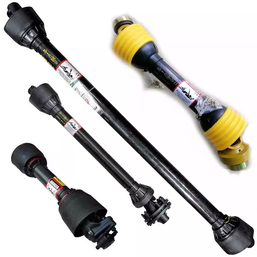
PTO Shaft Safety Chains
PTO shaft is the part of a tractor that helps transfer power from the tractor to the equipment it is hooked to. A PTO shaft is important if you have a tiller or bush hog. The correct PTO shaft size is crucial for both the tractor and the equipment. If the PTO shaft size is not correct for your equipment, it may not work.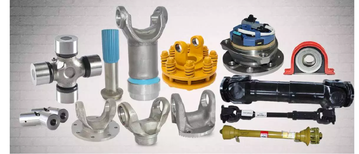
Safety chains
<br/Safety chains are an essential part of securing your PTO shaft. They prevent a rotating plastic shield from coming loose and causing injury or damage. It is important to protect your PTO and any other drive shafts on your machine. Watch the video below for more information about the dangers of unguarded PTOs.
PTOs are an efficient way to transfer mechanical power between tractors and implements. They helped revolutionize North American agriculture during the 1930s. Despite their convenience, PTOs have also proven to be one of the most common farm machinery hazards. This fact sheet outlines several important PTO safety precautions.
Safety chains for PTO shafts are necessary to protect both tractor and implement from damage. The PTO shaft must be attached properly to the tractor and the implement before starting the equipment. Before operating, be sure that the safety chains are positioned in a way that allows them to fully move. When operating the PTO, avoid being too aggressive as this can damage the drive line and shaft. For further safety, make sure to fit a torque limiter or clutch on the implement end of the PTO shaft.
PTOs are great for plowing, mowing, and shredding, but they also have potential to cause injuries if you don’t use a safety chain. It’s best to get a chain that is long enough to prevent injuries. Also, be sure that the PTO shaft does not compress completely at any point during the operating range. There should be several inches of overlap in the longest operating extension of the PTO.
Another common hazard with PTOs is IID shafts. While many machines and tractors have driveline guards, these are often missing. If you have a PTO with an IID, you should consider installing a safety chain.
Shield
A swingable tractor PTO shaft shield assembly consists of an inverted U-shaped shield member slidably attached to a bracket. It extends above the PTO shaft and has several notches and pins that engage each other. It can be held in a number of positions and can be retracted when not in use. It also includes a cover member that covers the space between the shield and tractor and abuts the raised portion of the shield member.
The PTO shaft shield is typically made of plastic, but it can also be made of metal. Plastic is less likely to break or damage than metal. The shield is supported by a bracket 51 with a curved distal end 57 and a non-metallic guard 59. When used in conjunction with a bracket, a PTO shaft shield should be properly installed to prevent damage to the shaft.
Keeping the PTO shaft shield in good condition is crucial to the safety of your tractor and your workers. An improperly installed PTO shaft shield can result in severe injuries. It may also ensnare or strike people in the vicinity. Proper maintenance will prevent many of these injuries. Equipment manufacturers have made great strides in reducing the risks of PTO mishaps. Operators are also responsible for keeping the shields in good condition. Removing the guards will only increase the risk to the operator.
A PTO shaft shield is a tubular assembly that is mounted on the tractor PTO shaft. It consists of two telescopic pieces that are held in place by shield support bearings. This shield protects the PTO shaft and the universal joints from debris and prevents premature wear. The shield can be easily removed and replaced if necessary.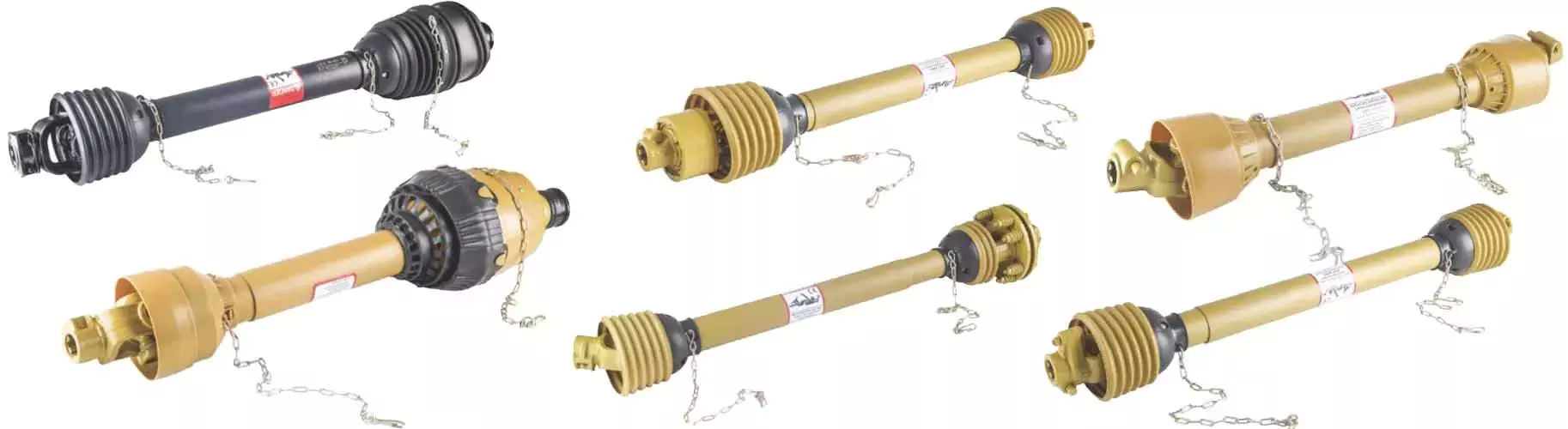
IID shaft guard
The IID shaft guard is a safety device used to protect PTO powered machinery from the possibility of separating while in use. The shaft, which is a telescoping shaft, is attached to the PTO stub on tractors. The telescopic feature is convenient when moving across uneven ground. However, this type of shaft can cause serious injury if it separates while in use.
The IID shaft guard can prevent these injuries by completely covering the shaft. The guard is made of metal or plastic and rotates along with the shaft. A person can react in less than five tenths of a second, making the IID shaft guard an important part of PTO safety.
PTO shafts rotate at speeds as high as 540 rpm, which is very fast. A limb could be wrapped around the driveline shaft, causing a serious injury or death. Because of the speed of a PTO, it can be difficult for an individual to discern whether it is engaged or not and may not be aware of the danger.
An IID shaft guard should be fitted to every tractor PTO shaft. It should be tested and rotated regularly. It is also important to keep the tractor engine off when working around the PTO shaft. Using a drawbar to protect driveline components is also important. It will prevent stress on the driveline and reduce the possibility of separation.
Overrunning clutch
An overrunning clutch on a PTO shaft is a mechanism that allows the PTO shaft to rotate freely in one direction while restricting the speed of the implement being hauled behind the tractor. This clutch is also useful for preventing the speed of the implement from exceeding the speed of the tractor while slowing down. It comes in two basic configurations, one for a clockwise and the other for a counter-clockwise direction.
Another type of overrun clutch is used on tractors with a PTO driven bush hog. A bush hog has a flywheel and blades that drive the transmission through the PTO shaft. Without an overrunning clutch, these implements would freewheel while the tractor is driving and would potentially break the shaft.
A PTO overrunning clutch prevents power from backfeeding into the transmission, the part that transmits power to the rear wheels. Without an overrunning clutch, the tractor could backfeed power, causing an accident if the blade assembly hits an object. As such, it is essential to use the overrunning clutch to ensure that your tractor will be safe.
Direction of rotation
Despite its name, the direction of rotation of a PTO shaft can change if necessary. Most PTOs have a single-direction rotation, but you can often reverse the direction by installing a reverse PTO adapter. However, you should only use reverse PTOs when absolutely necessary.
A standard PTO rotation direction has been defined by the International Organization for Standardization (ISO). It is considered necessary to adhere to this standard, as improper rotation can cause damage to implements attached to a PTO. This standard helps farmers avoid problems such as ruined implements. While the direction of rotation of a PTO shaft is not always the same for all PTOs, there are some tractors that allow it to rotate both ways, while others have no restrictions.
The direction of rotation of a PTO shaft can be changed by using a hydraulic pump. Another way to connect a PTO is through a “sandwich” type split shaft unit. These units are mounted between the transmission and engine, and they usually receive drive directly from the engine shaft. They can also deliver complete engine power to a PTO. However, you must modify your vehicle’s driveline to install such a split-shaft unit.

editor by CX 2023-07-13
China Custom ND Agricultural Aluminum Gearbox for Agriculture Conical Fertilizer Distributor/Salt Spreader Pto Gear Box pto shaft carrier bearing
Product Description
Product Description
Company Profile
In 2571, HangZhou CZPT Machinery Co.,ltd was established by Ms. Iris and her 2 partners(Mr. Tian and Mr. Yang) in HangZhou city(ZHangZhoug province, China), all 3 Founders are engineers who have more than averaged 30 years of experience. Then because the requirements of business expansion, in 2014, it moved to the current Xihu (West Lake) Dis. Industrial Zone (HangZhou city, ZHangZhoug province, China).
Through our CZPT brand ND, CZPT Machinery delivers agricultural solutions to agriculture machinery manufacturer and distributors CZPT through a full line of spiral bevel gearboxes, straight bevel gearboxes, spur gearboxes, drive shafts, sheet metal, hydraulic cylinder, motors, tyre, worm gearboxes, worm operators etc. Products can be customized as request.
We, CZPT machinery established a complete quality management system and sales service network to provide clients with high-quality products and satisfactory service. Our products are sold in 40 provinces and municipalities in China and 36 countries and regions in the world, our main market is the European market.
Certifications
Our Factory
Sample Room
Why choose us?
1) Customization: With a strong R&D team, and we can develop products as required. It only takes up to 7 days for us to design a set of drawings. The production time for new products is usually 50 days or less.
2) Quality: We have our own complete inspection and testing equipment, which can ensure the quality of the products.
3) Capacity: Our annual production capacity is over 500,000 sets, also, we also accept small quantity orders, to meet the needs of different customer’s purchase quantities.
4) Service: We focus on offering high-quality products. Our products are in line with international standards and are mainly exported to Europe, Australia, and other countries and regions.
5) Shipment: We are close to HangZhou and ZheJiang ports, to provide the fastest shipping service.
Packaging & Shipping
FAQ
Q: Are you a trading company or manufacturer?
A: We’re factory and providing gearbox ODM & OEM services for the European market for more than 10 years
Q: Do you provide samples? is it free or extra?
A: Yes, we could offer the sample for free charge but do not pay the cost of freight.
Q: How long is your delivery time? What is your terms of payment?
A: Generally it is 40-45 days. The time may vary depending on the product and the level of customization.
For standard products, the payment is: 30% T/T in advance,balance before shipment.
Q: What is the exact MOQ or price for your product?
A: As an OEM company, we can provide and adapt our products to a wide range of needs.
Thus, MOQ and price may greatly vary with size, material and further specifications; For instance, costly products or standard products will usually have a lower MOQ. Please contact us with all relevant details to get the most accurate quotation.
If you have another question, please feel free to contact us.
| Application: | Machinery, Agricultural Machinery, Fertilizer Sprayers Farm Spreader |
|---|---|
| Function: | Distribution Power, Change Drive Torque, Change Drive Direction, Speed Changing, Speed Reduction, Speed Increase |
| Layout: | Straight or Spiral Bevel Gear |
| Hardness: | Hardened Tooth Surface |
| Installation: | Vertical Type |
| Step: | Single-Step |
| Customization: |
Available
| Customized Request |
|---|
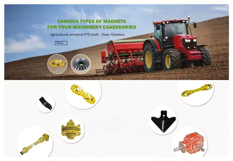
The Different Parts of a PTO Shaft
Power Take-Off (PTO) shafts are an integral part of a tractor’s driveline. Without them, a tractor cannot operate. It is essential to understand the different parts of a PTO shaft, as they are crucial for the operation of your tractor. These parts are typically overlooked during routine tractor maintenance checks, but knowing more about them will help you practice on farm machinery better.
Tractor’s power take-off (PTO) shaft
A Tractor’s power take-off (or PTO) shaft transfers power from the tractor to an implement. These shafts typically rotate at speeds between 540 and 1000 rpm. A number of safety features help prevent accidental contact between the shaft and the implement.
In order to avoid this problem, tractor operators should be vigilant while operating their tractors. They should make sure that the tractor’s power take-off (PTO) shaft is shielded. These shields include a master shield for the PTO stub, a PTO integral journal shield, and an implement input connection shield. The PTO master shield is mounted on the tractor and extends over the PTO stub on three sides. It is designed to prevent collisions between the tractor and any connected machine drive shaft.
A power take-off (PTO) shaft is an important component on any tractor. It is a shaft that transmits mechanical power from a tractor to an implement or separate machine. Early PTOs used a transmission and were located at the rear of the tractor. They are now available with hydraulic or mechanical drivelines. These power take-offs transfer the tractor’s power to a secondary piece of equipment through a driveshaft.
Proper PTO shaft guards protect people from stepping on rotating shafts. The PTO should not compress fully at any point in the operating range. It should have several inches of overlap at the maximum operating extension. A PTO guard should be positioned properly for each machine.
Despite these benefits, there are still many risks associated with PTO shafts. These powerful and potentially dangerous pieces of machinery can cause severe injury if not used safely. Luckily, proper installation of safety shields can reduce the risk of injury.
Types
PTO shafts come in a variety of different shapes, sizes, and materials. The most common types are square and round, but there are also star-shaped and trilobed types. While the star-shaped type is a typical North American design, the trilobed and lemon-shaped varieties are typically German or Italian. Typically, the lemon-shaped ones are made of an alloy called ‘Lemon Yellow.’ In some cases, the shaft will come with snap rings.
Different manufacturers use various materials for their PTO shafts. The tube of a welded drive shaft must be strong enough to handle the force exerted by the PTO. There are many different materials available, but some are stronger than others. Before choosing the type of drive shaft that is right for your machine, make sure that you know the exact measurements of your driveline.
When deciding between different types of PTO shafts, you must also consider the materials that will be used for your particular application. While splines are the most common material for PTO shafts, you can find various types that have different uses. Carbon steel is malleable and has a low carbon content, which makes it more reliable. A ferrous steel is more durable and contains metals like nickel, chromium, and molybdenum, which make it a great alternative to carbon steel.
A PTO gearbox input shaft extends between the PTO gearbox and the PTO clutch. It is mounted with a toothed wheel 8. An inductive sensor 9 on the shaft outputs a pulsed electronic signal based on the rotational speed of the shaft. These pulsed signals are called inductive speed sensors.
Rotation direction
The PTO shaft is a critical part of the power take-off of a farm tractor. It allows the tractor to transfer power from the engine to an implement such as a mower or other garden equipment. The rotation direction of the PTO shaft depends on the type of implement. Some implements only accept rotation in one direction, while others require rotation in both directions.
Safety chain
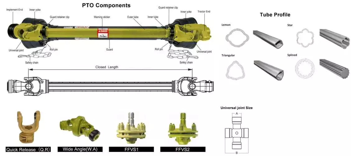 One of the best ways to protect your PTO shaft is to use a safety chain. A safety chain is a chain that is attached to the PTO shaft, and it prevents the plastic shield from spinning on the shaft. This chain should be fastened to a suitable point on your machine or tractor. It should not be attached to the lower lift arms or the U-guard.
PTO shafts can be very dangerous if they are not guarded. They can rotate as high as 1000 rpm and could seriously injure you. It is also important to ensure that the PTO shaft guard is fitted correctly, and that the tractor is turned off before working on it. In addition, avoiding wearing loose clothing when working around a PTO shaft can help protect your life.
Another way to protect the PTO shaft is to shield the IID shaft. This can be done by using shielding over the straight part of the shaft, the PTO connection, or the Implement Input Connection. A protruding bolt or pin can catch clothing and snag it. If not shielded, the clothing can wrap around the shaft, trapping the person against it.
A good safety chain should be positioned between the tractor and the PTO shaft. The chain should be at least 50 mm wider than the PTO shaft, and should be in good condition. It should cover the entire length of the PTO shaft from the tractor to the first bearing. The PTO shaft must also be fitted with the correct bearing ring. It is also vital to ensure that the PTO guard does not bend or break, as this could result in damage to the PTO shaft.
Shield
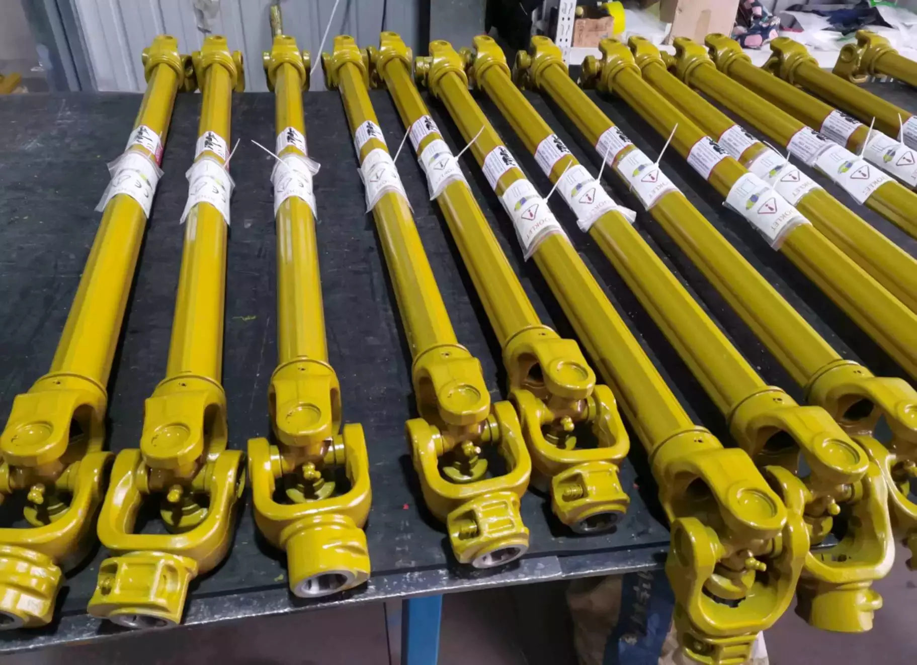 A PTO shaft shield protects the PTO shaft from possible impacts. It is typically made of plastic, but can also be made of metal. These shields are easy to damage, and are therefore preferably made of a durable material. The shields are held in place with brackets. The shields are made with two parts: an inner shield and a protective sleeve.
An improvement to the PTO shaft shield is a bracket that supports both the outer and PTO shaft. It is shown in conjunction with a towed machine in FIGS. 2 and 7. FIG. 7 is a side elevation of the bracket mounted to the tongue of the machine. This shield is designed to prevent the PTO shaft from becoming damaged during the towed process.
The main risk associated with PTO mishaps is entanglement, which can result in serious injuries. If a shaft separates from a tractor, it can strike nearby workers or people. Proper maintenance can minimize the risk of entanglement and save lives. Thankfully, equipment manufacturers have made huge strides in reducing the risk of these accidents. Operators should always make sure that the PTO shaft shield is in place to avoid the risk of entanglement.
In addition to preventing entanglement, a PTO shaft shield also helps protect the universal joints that are mounted on the PTO shaft. The shield is made of plastic or steel. It is typically shaped like an inverted U and covers both the top and sides of the shaft. A detachable PTO shaft shield is also available.
As with all parts of a PTO driveline, the PTO shaft shield should be maintained to prevent damage to the bearings. It is necessary to inspect the shield and replace it whenever it becomes damaged. PTO equipment is often used outdoors, and it is frequently exposed to crop debris, rust, and dirt that can affect the bearings. Proper maintenance will extend the equipment’s lifespan and reduce maintenance costs.
editor by CX 2023-07-12
China Custom ND Brand Agricultural Gearbox for Agriculture Land Imprinter Gear Box Pto pto shaft carrier bearing
Product Description
Product Description
Company Profile
In 2571, HangZhou CZPT Machinery Co.,ltd was established by Ms. Iris and her 2 partners(Mr. Tian and Mr. Yang) in HangZhou city(ZHangZhoug province, China), all 3 Founders are engineers who have more than averaged 30 years of experience. Then because the requirements of business expansion, in 2014, it moved to the current Xihu (West Lake) Dis. Industrial Zone (HangZhou city, ZHangZhoug province, China).
Through our CZPT brand ND, CZPT Machinery delivers agricultural solutions to agriculture machinery manufacturer and distributors CZPT through a full line of spiral bevel gearboxes, straight bevel gearboxes, spur gearboxes, drive shafts, sheet metal, hydraulic cylinder, motors, tyre, worm gearboxes, worm operators etc. Products can be customized as request.
We, CZPT machinery established a complete quality management system and sales service network to provide clients with high-quality products and satisfactory service. Our products are sold in 40 provinces and municipalities in China and 36 countries and regions in the world, our main market is the European market.
Certifications
Our Factory
Sample Room
Why choose us?
1) Customization: With a strong R&D team, and we can develop products as required. It only takes up to 7 days for us to design a set of drawings. The production time for new products is usually 50 days or less.
2) Quality: We have our own complete inspection and testing equipment, which can ensure the quality of the products.
3) Capacity: Our annual production capacity is over 500,000 sets, also, we also accept small quantity orders, to meet the needs of different customer’s purchase quantities.
4) Service: We focus on offering high-quality products. Our products are in line with international standards and are mainly exported to Europe, Australia, and other countries and regions.
5) Shipment: We are close to HangZhou and ZheJiang ports, to provide the fastest shipping service.
Packaging & Shipping
FAQ
Q: Are you a trading company or manufacturer?
A: We’re factory and providing gearbox ODM & OEM services for the European market for more than 10 years
Q: Do you provide samples? is it free or extra?
A: Yes, we could offer the sample for free charge but do not pay the cost of freight.
Q: How long is your delivery time? What is your terms of payment?
A: Generally it is 40-45 days. The time may vary depending on the product and the level of customization.
For standard products, the payment is: 30% T/T in advance,balance before shipment.
Q: What is the exact MOQ or price for your product?
A: As an OEM company, we can provide and adapt our products to a wide range of needs.
Thus, MOQ and price may greatly vary with size, material and further specifications; For instance, costly products or standard products will usually have a lower MOQ. Please contact us with all relevant details to get the most accurate quotation.
If you have another question, please feel free to contact us.
| Application: | Machinery, Agricultural Machinery |
|---|---|
| Function: | Distribution Power, Change Drive Torque, Change Drive Direction, Speed Changing, Speed Reduction, Speed Increase |
| Layout: | Straight or Spiral Bevel Gear |
| Hardness: | Hardened Tooth Surface |
| Installation: | Vertical Type |
| Step: | Single-Step |
| Customization: |
Available
| Customized Request |
|---|
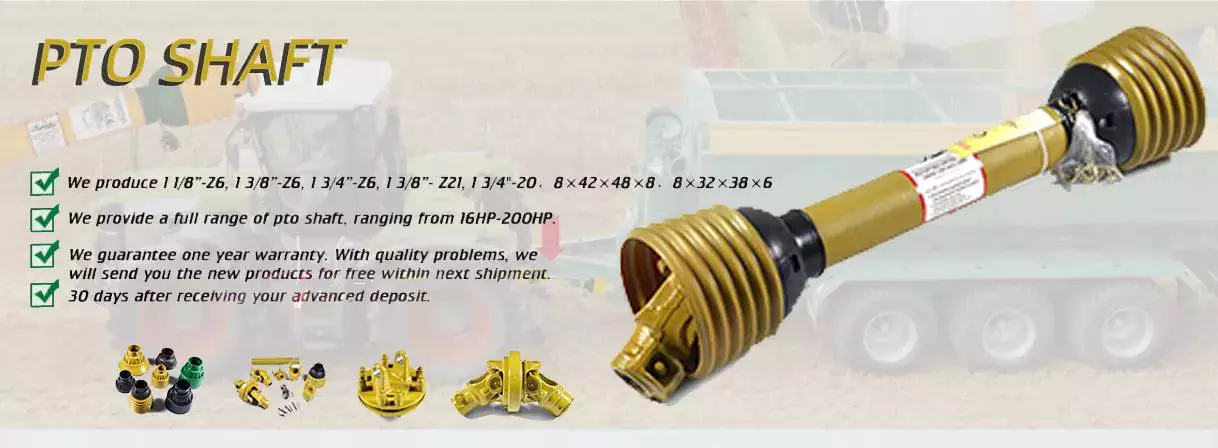
What Is a PTO Shaft?
A PTO shaft is a component that is important for a power take-off (PTO) tractor. There are many different kinds of PTOs, including Italian, German, and North American types. The types are categorized into different series, which will have different features such as bearing diameter, cap-to-cap length, and snap rings.
Power Take-Off (PTO) shaft
A PTO shaft is a high-speed working shaft that provides torque and lift. This is an advantage for machines that lift and lower loads and are often used on construction sites. Often, the operating elements are located outside of the operator’s cabin. A safety system is also present that allows the PTO shaft to automatically disengage if it is not turned on.
A safety retaining band 12 is used to secure the PTO shaft. The retaining band extends axially from the PTO shaft S and includes a hinge. The band may be adjustable in width to ensure a correct clearance from the PTO shaft. If necessary, it may also be secured with a conventional over-center clamp.
The power-take-off (PTO) shaft is a crucial part of a tractor. Understanding how power is transferred from the tractor’s engine to the implement requires a better understanding of how this shaft works. The torque and speed of the PTO shaft is essential to developing and utilizing the power of the tractor. There are many ways to measure torque and speed at the PTO shaft, including using a telemetry or encoder system.
A Power Take-Off (PTO) shaft safety retainer is an inexpensive, dependable, and fully effective device that protects the PTO shaft from entanglement. Its effectiveness will become clear after reading the specification. A power take-off shaft safety retainer is not difficult to install and is a good choice for many applications.
PTO shafts have a dangerous tendency to separate from the driven machinery. This poses a safety hazard because the PTO shaft can continue to whip around while the operator is driving the machine. Additionally, it can be very difficult for the operator to reach the power plant when operating PTO-driven equipment.
Safety chain
The safety chain on your PTO shaft is an important component of your tractor’s safety system. A properly guarded PTO can prevent entanglement with people, tools, and objects. Moreover, it reduces the risk of the PTO shaft becoming detached from the tractor. It also prevents people from stepping over the rotating shaft.
When not guarded, a PTO shaft is extremely dangerous. It can cause serious injuries and even death. Proper safety chains can prevent this from happening and protect livestock from damage to the PTO shaft. If you’re looking to purchase a safety chain for your PTO shaft, be sure to get one that fits tightly.
When properly attached, a safety chain can keep the shaft from swinging when the PTO is engaged. A 540-rpm PTO shaft will make more than two complete revolutions in less than five seconds. That means it can wrap someone in five tenths of a second. And if you try to pull away, you’ll get wrapped even tighter!
Another reason to use a safety chain is to prevent injury from clothing getting caught in the drive shaft. A jacket or a sweater can entangle itself around the PTO shaft and cause a serious injury. The clothing can also trap the injured limb against the shaft. Hence, the chain should be removed as soon as possible after the operation is completed.
A safety chain is an essential part of your tractor’s safety system. It prevents an accident from happening because of improper maintenance. A poorly maintained PTO shaft can result in severe injuries or even death. Properly installed and maintained safety chain can help you prevent any kind of PTO shaft accident.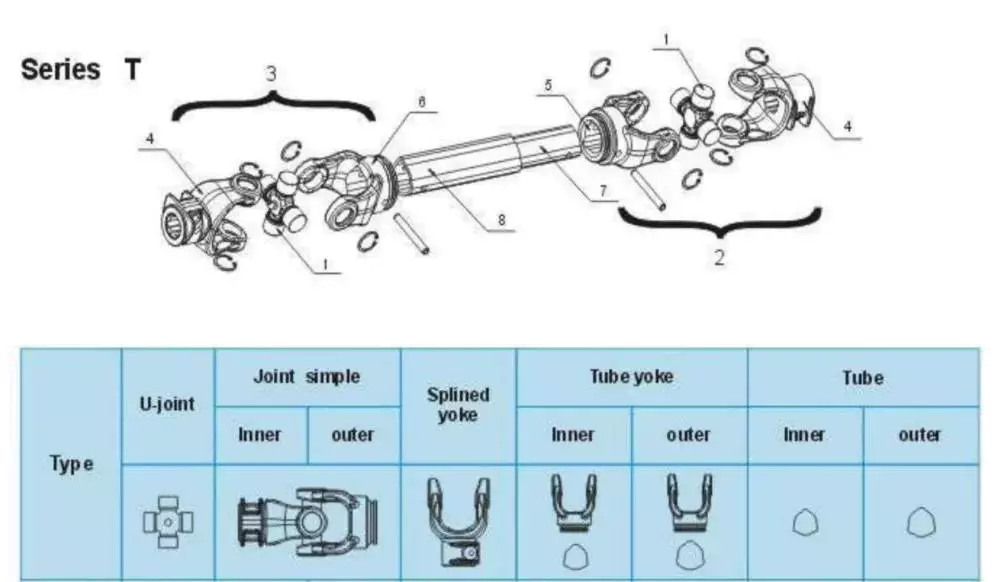
Universal joint
A bad universal joint can cause a number of problems for your tractor or implement. These issues may include squeaking or clunking noises when you shift gears, or a shuddering sensation when you brake. If you notice any of these symptoms, it is best to take your vehicle to a mechanic right away for a thorough inspection. If not fixed properly, a bad universal joint can separate from the drive shaft and cause major damage to the tractor or implement.
In order to choose the proper universal joint, you must consider the size of your PTO shaft. Some implements have a diameter of 14 inches or more from the hitch point to the end of the input shaft. The longer distance helps prevent the PTO shaft from bottoming out when making sharp turns. It also prevents the two parts of the shaft from detaching during cornering.
Universal joints are used in agricultural and forestry equipment and other vehicles with large number of rotors. They can be made of different materials. The most common is steel or stainless steel. This material can last for many years. A universal joint is an excellent option for small tractors, lawn mowers, and other agricultural equipment.
The universal joint is also very useful when coupling or extending drive lines. It comes with 2 yokes and a cross kit. The yokes measure 6 x 13/8″ spline, while the cross kit measures 30,2 x 92 mm. The universal joint is made to withstand extreme temperatures. It can be easily disassembled and serviced if necessary.
Square rigid shaft
Torsion is a property of a mechanical system that is affected by changes in torsional rigidity. Torsional rigidity is measured as the torque needed to twist one unit of angular measurement over one unit of length. A shaft with high torsional rigidity will provide a stable mechanical interface.
Different shafts may have different types of collars. The most basic one is a sleeve, which is composed of a thick tube with the same diameter as the shaft. The sleeve is attached to each end of the shaft and has threaded inserts to prevent longitudinal movement.
The PTO shaft also has a safety shield on both ends. It helps to prevent accidents by securing equipment to the tractor. It can be found in domestic and metric shapes. The domestic versions are generally round and domestic shaped, while metric versions are available in a bell, football, star, and metric shape.
An CZPT coupling consists of three pieces: a center plastic disc, two encompassing discs, and a flange. These parts are joined together with a ring that is screwed to the shaft. Some couplings feature oil injection points on the coupling. These can supply oil under pressure to the coupling’s annular grooves. This helps it ‘float’ and aids in the removal.
Another type of flexible coupling is the universal joint. These couplings can be made from a variety of materials, such as rubber, braided metal wire, or woven wire. They can be fabricated to withstand various misalignments. But, unlike rigid couplings, flexible couplings are susceptible to shock and vibration.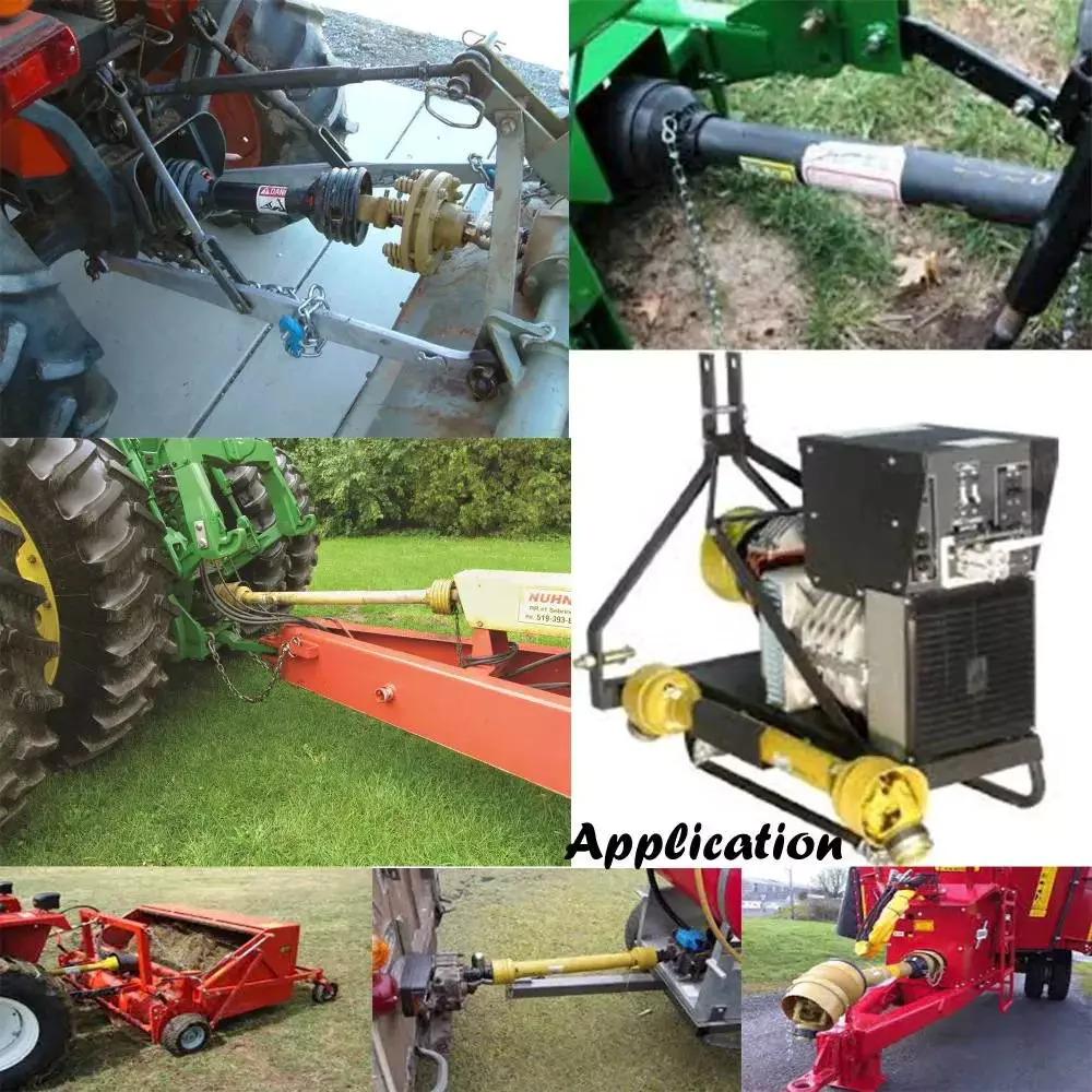
Economy PTO
Economy PTO shafts are designed to reduce the overall torque and power consumption of a tractor. They can be manually adjusted to engage and disengage the PTO. The cab mounted control/monitoring unit 14 has a switch 19 that selects between the economy and normal driving modes of the PTO. Using the economy mode decreases the engine rpm while using a lower gear ratio to drive the PTO shaft.
Economy PTO shafts come in hydraulic and mechanical versions. Both types are suitable for agricultural tractors. They allow the tractor to operate at a lower rpm, which reduces noise and vibration. They can also be used in a wide range of equipment. The transmission PTO is the oldest type, and is directly connected to the transmission. When the clutch is engaged, it drives the transmission.
Standard PTO shafts are available in various diameters, splines, and speeds. Many implements are designed to be compatible with one or more of these types of PTO shafts. The domestic versions come with a splined front shaft and a square, rectangle, or round secondary shaft.
Another difference between the two types is the number of teeth on the toothed wheel. The economy PTO allows the tractor to run at a lower rpm than the standard PTO. The engine rpm can go as low as 1600 while using the economy PTO. It also helps to reduce noise and vibration in the cab.
The present invention solves these issues and provides an increased level of automation and operator awareness of the PTO function. It also includes a system for detecting the type of PTO shaft and automatically setting the parameters of the control routine.
editor by CX 2023-07-11
China Chinese Factory Tractor Rotary Mowers Tillers Pto Shaft Reducer Gearbox for Farm and Agricultural Machinery slip clutch pto shaft
Merchandise Description
Tractor Rotary Mowers Bevel Fertilizer Spreader Tillers Right Angle Pto Shaft Reducer Gearbox for Farm and Agricultural Machinery
Proven in Nov.2002,HangZhou CZPT is a specialist manufacturer and provider in supplying spare parts and add-ons for agricultural equipment. In addition to the 3000 requirements components, we also provide our consumers tailor-made articles or blog posts or assemblies that are for special software.
HangZhou CZPT concentrated on the improvement and manufacturing of gearboxes with a specialist staff and continue to learn sophisticated technologies the use of first-course tools higher high quality offer chain technique, relying on these, the gearboxes get high reputation among consumers at house and abroad.
These gearboxes are commonly utilised in rotary tillers, lawn mowers, harvesters, gap diggers, pesticide sprayers, irrigation devices, fertilizer spreaders, blenders and so on. The primary products are:
–Straight bevel gearbox
–Spiral bevel gearbox
–Planetary reducer
–Worm gearbox
HangZhou CZPT Intercontinental Buying and selling Co.,Ltd is a modern day organization specilizing in the advancement, production, revenue and providers of PTO shaft. We adhere to the principle of “Precise Driveline, Advocate Environmentally friendly”, employing superior technologies and equipments to guarantee all the technological requirements of precise driveline. So that the transmission performance can be maxmized and each and every fall of source of customers’ can be saved. In the meantime, we have a buyer-centric support program, supplying a full assortment of pre-sale, sale and soon after-sale provider. Client pleasure is our forever pursuit.
We stick to the principle of people first, trying our very best to established up a enjoyable surroundings and system of performance for every personnel, so every person can be self-consciously energetic to be a part of in “Precise Driveline, Adocate Eco-friendly” to embody the self-well worth, business worth and social value.
Newnuro’s goal is: lowering customer’s purchase spending budget, assistance buyers to earn a lot more market.
Newnuro often finds remedy for buyers.Client satisfaction is our ultimate purpose and forever pursuit.
|
US $60 / Piece | |
10 Pieces (Min. Order) |
###
| Application: | Machinery, Agricultural Machinery |
|---|---|
| Function: | Distribution Power, Change Drive Torque, Change Drive Direction, Speed Changing, Speed Reduction, Speed Increase |
| Layout: | Assembled |
| Hardness: | Hardened Tooth Surface |
| Installation: | Horizontal Type |
| Step: | Single-Step |
###
| Samples: |
US$ 50/Piece
1 Piece(Min.Order) |
|---|
###
| Customization: |
Available
|
|---|
|
US $60 / Piece | |
10 Pieces (Min. Order) |
###
| Application: | Machinery, Agricultural Machinery |
|---|---|
| Function: | Distribution Power, Change Drive Torque, Change Drive Direction, Speed Changing, Speed Reduction, Speed Increase |
| Layout: | Assembled |
| Hardness: | Hardened Tooth Surface |
| Installation: | Horizontal Type |
| Step: | Single-Step |
###
| Samples: |
US$ 50/Piece
1 Piece(Min.Order) |
|---|
###
| Customization: |
Available
|
|---|
The Different Parts of a PTO Shaft
Power Take-Off (PTO) shafts are an integral part of a tractor’s driveline. Without them, a tractor cannot operate. It is essential to understand the different parts of a PTO shaft, as they are crucial for the operation of your tractor. These parts are typically overlooked during routine tractor maintenance checks, but knowing more about them will help you practice on farm machinery better.
Tractor’s power take-off (PTO) shaft
A Tractor’s power take-off (or PTO) shaft transfers power from the tractor to an implement. These shafts typically rotate at speeds between 540 and 1000 rpm. A number of safety features help prevent accidental contact between the shaft and the implement.
In order to avoid this problem, tractor operators should be vigilant while operating their tractors. They should make sure that the tractor’s power take-off (PTO) shaft is shielded. These shields include a master shield for the PTO stub, a PTO integral journal shield, and an implement input connection shield. The PTO master shield is mounted on the tractor and extends over the PTO stub on three sides. It is designed to prevent collisions between the tractor and any connected machine drive shaft.
A power take-off (PTO) shaft is an important component on any tractor. It is a shaft that transmits mechanical power from a tractor to an implement or separate machine. Early PTOs used a transmission and were located at the rear of the tractor. They are now available with hydraulic or mechanical drivelines. These power take-offs transfer the tractor’s power to a secondary piece of equipment through a driveshaft.
Proper PTO shaft guards protect people from stepping on rotating shafts. The PTO should not compress fully at any point in the operating range. It should have several inches of overlap at the maximum operating extension. A PTO guard should be positioned properly for each machine.
Despite these benefits, there are still many risks associated with PTO shafts. These powerful and potentially dangerous pieces of machinery can cause severe injury if not used safely. Luckily, proper installation of safety shields can reduce the risk of injury.
Types
PTO shafts come in a variety of different shapes, sizes, and materials. The most common types are square and round, but there are also star-shaped and trilobed types. While the star-shaped type is a typical North American design, the trilobed and lemon-shaped varieties are typically German or Italian. Typically, the lemon-shaped ones are made of an alloy called ‘Lemon Yellow.’ In some cases, the shaft will come with snap rings.
Different manufacturers use various materials for their PTO shafts. The tube of a welded drive shaft must be strong enough to handle the force exerted by the PTO. There are many different materials available, but some are stronger than others. Before choosing the type of drive shaft that is right for your machine, make sure that you know the exact measurements of your driveline.
When deciding between different types of PTO shafts, you must also consider the materials that will be used for your particular application. While splines are the most common material for PTO shafts, you can find various types that have different uses. Carbon steel is malleable and has a low carbon content, which makes it more reliable. A ferrous steel is more durable and contains metals like nickel, chromium, and molybdenum, which make it a great alternative to carbon steel.
A PTO gearbox input shaft extends between the PTO gearbox and the PTO clutch. It is mounted with a toothed wheel 8. An inductive sensor 9 on the shaft outputs a pulsed electronic signal based on the rotational speed of the shaft. These pulsed signals are called inductive speed sensors.
Rotation direction
The PTO shaft is a critical part of the power take-off of a farm tractor. It allows the tractor to transfer power from the engine to an implement such as a mower or other garden equipment. The rotation direction of the PTO shaft depends on the type of implement. Some implements only accept rotation in one direction, while others require rotation in both directions.
Safety chain
One of the best ways to protect your PTO shaft is to use a safety chain. A safety chain is a chain that is attached to the PTO shaft, and it prevents the plastic shield from spinning on the shaft. This chain should be fastened to a suitable point on your machine or tractor. It should not be attached to the lower lift arms or the U-guard.
PTO shafts can be very dangerous if they are not guarded. They can rotate as high as 1000 rpm and could seriously injure you. It is also important to ensure that the PTO shaft guard is fitted correctly, and that the tractor is turned off before working on it. In addition, avoiding wearing loose clothing when working around a PTO shaft can help protect your life.
Another way to protect the PTO shaft is to shield the IID shaft. This can be done by using shielding over the straight part of the shaft, the PTO connection, or the Implement Input Connection. A protruding bolt or pin can catch clothing and snag it. If not shielded, the clothing can wrap around the shaft, trapping the person against it.
A good safety chain should be positioned between the tractor and the PTO shaft. The chain should be at least 50 mm wider than the PTO shaft, and should be in good condition. It should cover the entire length of the PTO shaft from the tractor to the first bearing. The PTO shaft must also be fitted with the correct bearing ring. It is also vital to ensure that the PTO guard does not bend or break, as this could result in damage to the PTO shaft.
Shield
A PTO shaft shield protects the PTO shaft from possible impacts. It is typically made of plastic, but can also be made of metal. These shields are easy to damage, and are therefore preferably made of a durable material. The shields are held in place with brackets. The shields are made with two parts: an inner shield and a protective sleeve.
An improvement to the PTO shaft shield is a bracket that supports both the outer and PTO shaft. It is shown in conjunction with a towed machine in FIGS. 2 and 7. FIG. 7 is a side elevation of the bracket mounted to the tongue of the machine. This shield is designed to prevent the PTO shaft from becoming damaged during the towed process.
The main risk associated with PTO mishaps is entanglement, which can result in serious injuries. If a shaft separates from a tractor, it can strike nearby workers or people. Proper maintenance can minimize the risk of entanglement and save lives. Thankfully, equipment manufacturers have made huge strides in reducing the risk of these accidents. Operators should always make sure that the PTO shaft shield is in place to avoid the risk of entanglement.
In addition to preventing entanglement, a PTO shaft shield also helps protect the universal joints that are mounted on the PTO shaft. The shield is made of plastic or steel. It is typically shaped like an inverted U and covers both the top and sides of the shaft. A detachable PTO shaft shield is also available.
As with all parts of a PTO driveline, the PTO shaft shield should be maintained to prevent damage to the bearings. It is necessary to inspect the shield and replace it whenever it becomes damaged. PTO equipment is often used outdoors, and it is frequently exposed to crop debris, rust, and dirt that can affect the bearings. Proper maintenance will extend the equipment’s lifespan and reduce maintenance costs.
editor by czh 2023-01-05
China Best Sales Agricultural Sickle Forage Harvester For Sale Tractor Rear Mounted Three-point Suspension Reciprocating Reinforced Square Mower agricultural pto gearbox
Situation: New
Application: Forage Grass
Functioning Width(mm): 1800 mm
Tractor Electricity(HP): twelve – fifty HP
Equipment Sort: Forage Machinery
Type: Sickle Bar Mower
Drive Variety: PTO Shaft Drive, PTO Push
Usage: Straw Mower
Fat: 180Kg
Certificate: Ce
Important Offering Factors: Substantial Productiveness
Warranty: 1 Year
Marketing Type: Sizzling Merchandise 2571
Video outgoing-inspection: Presented
Equipment Check Report: Presented
Guarantee of core components: 1 12 months
Core Components: Gearbox, Knife
Showroom Place: None
Relevant Industries: Farms, Property Use, Yard
Merchandise name: Reciprocating Square Mower
Cutting width (mm): 1800Mm
Design: 9GB-1.8
Colour: Consumer Need
Crucial phrases: Sickle Bar Mower
Stubble Height: 50-80Mm
Linkage: A few Stage Mounted
Operating pace: 540 R/Min
Soon after-income Support Presented: Video clip technological support, On the internet assistance
Right after Guarantee Provider: Spare parts
Regional Service Location: None
Packaging Information: Iron Body Deal/Wooden Box Bundle
Port: Every single Port In China
Agricultural Sickle Forage Harvester For Sale /Tractor Rear Mounted Three-position Suspension Reciprocating Bolstered Sq. Mower
The 9GB collection lawn mower produced and produced by Xihu (West Lake) Dis.g equipment is a rear mounted semi suspended (suspended) reciprocating lawn mower, which can be equipped with twelve-50 horsepower tractors. The utility model utilizes the offset crank connecting rod mechanism to drive the cutter to lower grass, which is suitable for flat grassland in agriculture, SWL worm bolt lifter jack screw gearbox harmonic push reducer cycloidal equipment box .5hp motor gearbox lg washing machine gearbo forestry and pastoral places, sloping land, hills and other different circumstances. It is employed for harvesting all-natural forage and planting forage, alfalfa, reed, green fodder, and so forth., and can also create massive garden such as manor, NMRV030 nmrv050 worm gearbox small reducer nmrv box equipment worm aluminum housing light weight reducer golfing training course, and so forth.
Excellent Features
The tractor’s electrical power output shaft drives the slicing motion of the cutter, the 3-position linkage controls the increase and slide of the apply, and controls the tractor’s electrical power output system to recognize the motion or end of the cutter. The cutter is operated by a single tractor driver with good mobility. The equipment has the characteristics of compact composition, convenient operation, powerful cutting, Agricultural machinery bearing deep groove ball bearing LM60P3049 ball bearing alternative for John Deere, CLAAS, CNH reduced stubble and neat chopping.
Solution Parameters
| Identify | Reciprocating Mower / Sickle Bar Mower | |||
| Design | 9GB-1.four | 9GB-1.six | 9GB-1.eight | 9GB-2.1 |
| Chopping Width | 1400Mm | 1600Mm | 1800Mm | 2100Mm |
| Slicing Peak | 50-80Mm | |||
| Doing work Pace | 4-10Km/h | |||
| PTO Pace | 540R/min | |||
| Matched Power | 12-40Hp | |||
| Cutter Stroke | 76 | |||
| Linkage | Three Level Mounted | |||
| Excess weight | 160Kg | 180Kg | 190Kg | 210Kg |
Depth Drawing
Relevant Forage Machinery
Manufacturing unit Corner
Company Information
Solution Certification
FAQ
Calculating the Deflection of a Worm Shaft
In this article, we’ll discuss how to calculate the deflection of a worm gear’s worm shaft. We’ll also discuss the characteristics of a worm gear, including its tooth forces. And we’ll cover the important characteristics of a worm gear. Read on to learn more! Here are some things to consider before purchasing a worm gear. We hope you enjoy learning! After reading this article, you’ll be well-equipped to choose a worm gear to match your needs.
Calculation of worm shaft deflection
The main goal of the calculations is to determine the deflection of a worm. Worms are used to turn gears and mechanical devices. This type of transmission uses a worm. The worm diameter and the number of teeth are inputted into the calculation gradually. Then, a table with proper solutions is shown on the screen. After completing the table, you can then move on to the main calculation. You can change the strength parameters as well.
The maximum worm shaft deflection is calculated using the finite element method (FEM). The model has many parameters, including the size of the elements and boundary conditions. The results from these simulations are compared to the corresponding analytical values to calculate the maximum deflection. The result is a table that displays the maximum worm shaft deflection. The tables can be downloaded below. You can also find more information about the different deflection formulas and their applications.
The calculation method used by DIN EN 10084 is based on the hardened cemented worm of 16MnCr5. Then, you can use DIN EN 10084 (CuSn12Ni2-C-GZ) and DIN EN 1982 (CuAl10Fe5Ne5-C-GZ). Then, you can enter the worm face width, either manually or using the auto-suggest option.
Common methods for the calculation of worm shaft deflection provide a good approximation of deflection but do not account for geometric modifications on the worm. While Norgauer’s 2021 approach addresses these issues, it fails to account for the helical winding of the worm teeth and overestimates the stiffening effect of gearing. More sophisticated approaches are required for the efficient design of thin worm shafts.
Worm gears have a low noise and vibration compared to other types of mechanical devices. However, worm gears are often limited by the amount of wear that occurs on the softer worm wheel. Worm shaft deflection is a significant influencing factor for noise and wear. The calculation method for worm gear deflection is available in ISO/TR 14521, DIN 3996, and AGMA 6022.
The worm gear can be designed with a precise transmission ratio. The calculation involves dividing the transmission ratio between more stages in a gearbox. Power transmission input parameters affect the gearing properties, as well as the material of the worm/gear. To achieve a better efficiency, the worm/gear material should match the conditions that are to be experienced. The worm gear can be a self-locking transmission.
The worm gearbox contains several machine elements. The main contributors to the total power loss are the axial loads and bearing losses on the worm shaft. Hence, different bearing configurations are studied. One type includes locating/non-locating bearing arrangements. The other is tapered roller bearings. The worm gear drives are considered when locating versus non-locating bearings. The analysis of worm gear drives is also an investigation of the X-arrangement and four-point contact bearings.
Influence of tooth forces on bending stiffness of a worm gear
The bending stiffness of a worm gear is dependent on tooth forces. Tooth forces increase as the power density increases, but this also leads to increased worm shaft deflection. The resulting deflection can affect efficiency, wear load capacity, and NVH behavior. Continuous improvements in bronze materials, lubricants, and manufacturing quality have enabled worm gear manufacturers to produce increasingly high power densities.
Standardized calculation methods take into account the supporting effect of the toothing on the worm shaft. However, overhung worm gears are not included in the calculation. In addition, the toothing area is not taken into account unless the shaft is designed next to the worm gear. Similarly, the root diameter is treated as the equivalent bending diameter, but this ignores the supporting effect of the worm toothing.
A generalized formula is provided to estimate the STE contribution to vibratory excitation. The results are applicable to any gear with a meshing pattern. It is recommended that engineers test different meshing methods to obtain more accurate results. One way to test tooth-meshing surfaces is to use a finite element stress and mesh subprogram. This software will measure tooth-bending stresses under dynamic loads.
The effect of tooth-brushing and lubricant on bending stiffness can be achieved by increasing the pressure angle of the worm pair. This can reduce tooth bending stresses in the worm gear. A further method is to add a load-loaded tooth-contact analysis (CCTA). This is also used to analyze mismatched ZC1 worm drive. The results obtained with the technique have been widely applied to various types of gearing.
In this study, we found that the ring gear’s bending stiffness is highly influenced by the teeth. The chamfered root of the ring gear is larger than the slot width. Thus, the ring gear’s bending stiffness varies with its tooth width, which increases with the ring wall thickness. Furthermore, a variation in the ring wall thickness of the worm gear causes a greater deviation from the design specification.
To understand the impact of the teeth on the bending stiffness of a worm gear, it is important to know the root shape. Involute teeth are susceptible to bending stress and can break under extreme conditions. A tooth-breakage analysis can control this by determining the root shape and the bending stiffness. The optimization of the root shape directly on the final gear minimizes the bending stress in the involute teeth.
The influence of tooth forces on the bending stiffness of a worm gear was investigated using the CZPT Spiral Bevel Gear Test Facility. In this study, multiple teeth of a spiral bevel pinion were instrumented with strain gages and tested at speeds ranging from static to 14400 RPM. The tests were performed with power levels as high as 540 kW. The results obtained were compared with the analysis of a three-dimensional finite element model.
Characteristics of worm gears
Worm gears are unique types of gears. They feature a variety of characteristics and applications. This article will examine the characteristics and benefits of worm gears. Then, we’ll examine the common applications of worm gears. Let’s take a look! Before we dive in to worm gears, let’s review their capabilities. Hopefully, you’ll see how versatile these gears are.
A worm gear can achieve massive reduction ratios with little effort. By adding circumference to the wheel, the worm can greatly increase its torque and decrease its speed. Conventional gearsets require multiple reductions to achieve the same reduction ratio. Worm gears have fewer moving parts, so there are fewer places for failure. However, they can’t reverse the direction of power. This is because the friction between the worm and wheel makes it impossible to move the worm backwards.
Worm gears are widely used in elevators, hoists, and lifts. They are particularly useful in applications where stopping speed is critical. They can be incorporated with smaller brakes to ensure safety, but shouldn’t be relied upon as a primary braking system. Generally, they are self-locking, so they are a good choice for many applications. They also have many benefits, including increased efficiency and safety.
Worm gears are designed to achieve a specific reduction ratio. They are typically arranged between the input and output shafts of a motor and a load. The two shafts are often positioned at an angle that ensures proper alignment. Worm gear gears have a center spacing of a frame size. The center spacing of the gear and worm shaft determines the axial pitch. For instance, if the gearsets are set at a radial distance, a smaller outer diameter is necessary.
Worm gears’ sliding contact reduces efficiency. But it also ensures quiet operation. The sliding action limits the efficiency of worm gears to 30% to 50%. A few techniques are introduced herein to minimize friction and to produce good entrance and exit gaps. You’ll soon see why they’re such a versatile choice for your needs! So, if you’re considering purchasing a worm gear, make sure you read this article to learn more about its characteristics!
An embodiment of a worm gear is described in FIGS. 19 and 20. An alternate embodiment of the system uses a single motor and a single worm 153. The worm 153 turns a gear which drives an arm 152. The arm 152, in turn, moves the lens/mirr assembly 10 by varying the elevation angle. The motor control unit 114 then tracks the elevation angle of the lens/mirr assembly 10 in relation to the reference position.
The worm wheel and worm are both made of metal. However, the brass worm and wheel are made of brass, which is a yellow metal. Their lubricant selections are more flexible, but they’re limited by additive restrictions due to their yellow metal. Plastic on metal worm gears are generally found in light load applications. The lubricant used depends on the type of plastic, as many types of plastics react to hydrocarbons found in regular lubricant. For this reason, you need a non-reactive lubricant.
