Product Description
Company Profile:
HangZhou CHINAMFG Machinery Co.,Ltd was founded in 2571. It locates at HangZhou city of ZheJiang province, which is about 1 hour far from ZheJiang city by fast train. Our company is a professional manufacturer for farm machinery, and now we have 7600 m² space factory and more than 80 workers, including more than 5 technicians with a 210 acres of agricultural machinery and agronomic experimental bases, to test product performance in strict accordance with scientific norms for getting better quality and faster delivery.
Main Products:
Our company has 8 categories of products for (Agriculture, orchards, gardens, animal husbandry, minor works, vegetables, forests, snow removal, etc.) which over 300 models of various agricultural implements, such as backhoe, loaders, rotary tillers, post hole digger, mower, snow blade, plough and other kinds to export to the 53 countries in Europe, Australia, America, south Africa, etc.
Enterprise awards and patented technology:
In November 2016, we were awarded “High-tech Enterprise” in ZheJiang Province. It is also a small and medium-sized technology innovation enterprise in HangZhou City, a private technology enterprise, and an excellent industrial enterprise in Yaoguan Town, HangZhou.
In addition, our company has also won 69 national patents, including 3 invention patents, 58 utility model patents and 8 other patents.
Product Description:
Perfect for use after storms when debris is scattered throughout areas usually maintained with normal mowers~ Multi-purpose machines for mulching sticks~ Ideal for thick grass, sticks, undergrowth and light vine mulching~ Vegetable & pasture topping~ Roadside maintenance.
Specifications:
| MODEL | EF85 | EF95 | EF105 | EF115 | EF125 | |
| Structure Weight | 100kg | 115kg | 130kg | 145kg | 160kg | |
| Working Width | 829mm | 929mm | 1571mm | 1129mm | 1229mm | |
| PTO Turning Speed | 540r/min | 540r/min | 540r/min | 540r/min | 540r/min | |
| Flail Type | Hammer/Y Blade | |||||
| Number of Flail | Hammer 12 /Y Blade 24 | Hammer 18 /Y Blade 36 | Hammer 18 /Y Blade 36 | Hammer 18 /Y Blade 36 | Hammer 18 /Y Blade 36 | |
| Tractor HP | 14-18hp | 16-20hp | 20-30hp | 20-30hp | 25-35hp | |
| MODEL | EF135 | EF145 | EF155 | EF165 | EF175 | |
| Structure Weight | 175kg | 190kg | 210kg | 235kg | 255kg | |
| Working Width | 1329mm | 1429mm | 1529mm | 1629mm | 1729mm | |
| PTO Turning Speed | 540r/min | 540r/min | 540r/min | 540r/min | 540r/min | |
| Flail Type | Y Blade/Hammer | |||||
| Number of Flail | Hammer 24 /Y Blade48 | Hammer 24 /Y Blade48 | Hammer 24 /Y Blade48 | Hammer 24 /Y Blade48 | Hammer 30 /Y Blade 60 | |
| Tractor HP | 25-35hp | 25-35hp | 30-40hp | 30-40hp | 30-40hp | |
Factory and Production Situation:
CE Certification:
Packing&Loading:
Your Professional Manufacturer of Tractor &ATV,UTV Implements (front end loader, backhoe, mower, rotary tiller, wood chipper,snow plow and so on, aslo OEM service provided)
HangZhou CHINAMFG Machinery Co.,Ltd
/* January 22, 2571 19:08:37 */!function(){function s(e,r){var a,o={};try{e&&e.split(“,”).forEach(function(e,t){e&&(a=e.match(/(.*?):(.*)$/))&&1
| Type: | Professional Mowers |
|---|---|
| Moving Way: | Tractor-Mounted |
| Cutter Type: | Rotary Lawn Mower |
| Applicable Area: | 500-1000m² |
| Feature: | 2-Stroke, Steel Chassis |
| Certification: | CE |
| Customization: |
Available
| Customized Request |
|---|

How do PTO shafts ensure efficient power transfer while maintaining safety?
PTO (Power Take-Off) shafts play a crucial role in ensuring efficient power transfer from a power source to driven machinery or equipment, while also maintaining safety. These shafts are designed with various features and mechanisms to optimize power transmission efficiency and mitigate potential hazards. Here’s a detailed explanation of how PTO shafts achieve efficient power transfer while prioritizing safety:
1. Mechanical Power Transmission: PTO shafts serve as mechanical linkages between the power source, typically a tractor or engine, and the driven machinery. They transmit rotational power from the power source to the equipment, enabling efficient transfer of energy. The mechanical design of PTO shafts, including their diameter, length, and material composition, is optimized to minimize power losses during transmission, ensuring that a significant portion of the power generated by the source is effectively delivered to the machinery.
2. Universal Joints and Flexible Couplings: PTO shafts are equipped with universal joints and flexible couplings that allow for angular misalignment and flexibility in movement. Universal joints accommodate variations in the alignment between the power source and the driven machinery, enabling smooth power transfer even when the two components are not perfectly aligned. Flexible couplings help to compensate for slight misalignments, reduce vibration, and prevent excessive stress on the shaft and connected components, thereby enhancing efficiency and reducing the risk of mechanical failure or damage.
3. Constant Velocity (CV) Joints: CV joints are often used in PTO shafts to maintain constant speed and torque transfer, particularly in applications where the driven machinery requires flexibility or operates at different angles. CV joints allow for smooth power transmission without significant fluctuations, even when the driven machinery is at an angle relative to the power source. By minimizing speed variations and power loss due to changing angles, CV joints contribute to efficient power transfer while ensuring consistent performance and reducing the likelihood of mechanical stress or premature wear.
4. Safety Guards and Shields: Safety is a paramount consideration in the design of PTO shafts. Protective guards and shields are installed to cover the rotating shaft and other moving parts. These guards act as physical barriers to prevent accidental contact with the rotating components, significantly reducing the risk of entanglement, injury, or damage. Safety guards are typically made of durable materials such as metal or plastic and are designed to allow the necessary movement for power transmission while providing adequate protection. Regular inspection and maintenance of these guards are crucial to ensure their effectiveness in maintaining safety.
5. Shear Bolt or Slip Clutch Mechanisms: PTO shafts often incorporate shear bolt or slip clutch mechanisms as safety features to protect the driveline components and prevent damage in case of excessive torque or sudden resistance. Shear bolts are designed to shear or break when the torque exceeds a predetermined threshold, disconnecting the PTO shaft from the power source. This helps prevent damage to the shaft, driven machinery, and power source. Slip clutches work similarly by allowing the PTO shaft to slip when excessive resistance is encountered, protecting the components from overload. These mechanisms act as safety measures to maintain the integrity of the PTO shaft and associated equipment while minimizing the risk of mechanical failures or accidents.
6. Compliance with Safety Standards: PTO shafts are designed and manufactured to comply with relevant safety standards and regulations. Manufacturers follow guidelines and requirements set by organizations such as the American Society of Agricultural and Biological Engineers (ASABE) or other regional safety authorities. Compliance with these standards ensures that PTO shafts meet specific safety criteria, including torque capacity, guard design, and other safety considerations. Users can rely on standardized PTO shafts that have undergone testing and certification, providing an additional layer of assurance regarding their safety and performance.
7. Operator Education and Training: To ensure safe and efficient operation, it is essential for operators to receive proper education and training on PTO shafts. Operators should be familiar with the specific safety features, maintenance requirements, and safe operating procedures for the PTO shafts used in their applications. This includes understanding the importance of using appropriate personal protective equipment, regularly inspecting the equipment for wear or damage, and following recommended maintenance schedules. Operator awareness and adherence to safety protocols significantly contribute to maintaining a safe working environment and maximizing the efficiency of power transfer.
In summary, PTO shafts ensure efficient power transfer while maintaining safety through their mechanical design, incorporation of universal joints and CV joints, installation of safety guards and shields, implementation of shear bolt or slip clutch mechanisms, compliance with safety standards, and operator education. By combining these features and practices, PTO shafts provide reliable and secure power transmission, minimizing power losses and potential risks associated with their operation.

What safety precautions should be followed when working with PTO shafts?
Working with Power Take-Off (PTO) shafts requires strict adherence to safety precautions to prevent accidents and ensure the well-being of individuals operating or working in the vicinity of the equipment. PTO shafts involve rotating machinery and can pose significant hazards if not handled properly. Here are several important safety precautions that should be followed when working with PTO shafts:
1. Familiarize Yourself with the Equipment: Prior to operating or working near a PTO shaft, it is crucial to thoroughly understand the equipment’s operation, including the specific PTO shaft configuration, safety features, and any associated machinery. Read and follow the manufacturer’s instructions and safety guidelines pertaining to the PTO shaft and associated equipment. Training and familiarity with the equipment are essential to ensure safe practices.
2. Wear Appropriate Personal Protective Equipment (PPE): When working with PTO shafts, individuals should wear appropriate personal protective equipment to minimize the risk of injury. This may include safety glasses, hearing protection, gloves, and sturdy footwear. PPE protects against potential hazards such as flying debris, noise, and accidental contact with rotating components.
3. Guarding and Shielding: Ensure that the PTO shaft and associated machinery are equipped with appropriate guarding and shielding. Guarding helps prevent accidental contact with rotating parts, reducing the risk of entanglement or injury. PTO shafts should have guard shields covering the rotating shaft and any exposed universal joints. Machinery driven by the PTO shaft should also have adequate guarding in place to protect against contact with moving parts.
4. Securely Fasten and Align PTO Shaft Components: Before operating or connecting the PTO shaft, ensure that all components are securely fastened and aligned. Loose or misaligned components can lead to shaft dislodgement, imbalance, and potential failure. Follow the manufacturer’s guidelines for proper installation and tightening of couplings, yokes, and other connecting points. Proper alignment is crucial to prevent excessive stress, vibrations, and premature wear on the PTO shaft and associated equipment.
5. Avoid Loose Clothing and Jewelry: Loose clothing, jewelry, or other items that can become entangled in the PTO shaft or associated machinery should be avoided. Secure long hair, tuck in loose clothing, and remove or properly secure any dangling accessories. Loose items can get caught in rotating parts, leading to serious injury or entanglement hazards.
6. Do Not Modify or Remove Safety Features: PTO shafts are equipped with safety features such as guard shields, safety covers, and torque limiters for a reason. These features are designed to protect against potential hazards and should not be modified, bypassed, or removed. Altering or disabling safety features can significantly increase the risk of accidents and injury. If any safety features are damaged or not functioning correctly, they should be repaired or replaced promptly.
7. Shut Down Power Source Before Maintenance: Before performing any maintenance, repairs, or adjustments on the PTO shaft or associated machinery, ensure that the power source is completely shut down and disconnected. This includes turning off the engine, disconnecting power supply, and engaging any safety locks or mechanisms. Lockout/tagout procedures should be followed to prevent accidental energization or startup during maintenance activities.
8. Regular Maintenance and Inspection: Regular maintenance and inspection of the PTO shaft and associated equipment are vital for safe operation. Follow the manufacturer’s recommended maintenance schedule and perform routine inspections to identify any signs of wear, damage, or misalignment. Lubricate universal joints as per the manufacturer’s guidelines to ensure smooth operation. Promptly address any maintenance or repair needs to prevent potential hazards.
9. Training and Communication: Ensure that individuals operating or working near PTO shafts receive proper training on safe work practices, hazard identification, and emergency procedures. Promote clear communication regarding the presence and operation of PTO shafts to prevent accidental contact or interference. Establish effective communication methods, such as signals or radios, when working in teams or near noisy equipment.
10. Be Aware of Surroundings: Maintain situational awareness when working with PTO shafts. Be mindful of the location of bystanders, obstacles, and potential hazards. Ensure a clear and safe work area around the PTO shaft. Avoid distractions and focus on the task at hand to prevent accidents caused by inattention.
By following these safety precautions, individuals can minimize the risk of accidents and injuries when working with PTO shafts. Safety should always be the top priority to ensure a safe and productive work environment.

How do PTO shafts handle variations in speed and torque requirements?
PTO shafts (Power Take-Off shafts) are designed to handle variations in speed and torque requirements between the power source (such as a tractor or engine) and the driven machinery or equipment. They incorporate various mechanisms and components to ensure efficient power transmission while accommodating the different speed and torque demands. Here’s a detailed explanation of how PTO shafts handle variations in speed and torque requirements:
1. Gearbox Systems: PTO shafts often incorporate gearbox systems to match the speed and torque requirements between the power source and the driven machinery. Gearboxes allow for speed reduction or increase and can also change the rotational direction if necessary. By using different gear ratios, PTO shafts can adapt the rotational speed and torque output to suit the specific requirements of the driven equipment. Gearbox systems enable PTO shafts to provide the necessary power and speed compatibility between the power source and the machinery they drive.
2. Shear Bolt Mechanisms: Some PTO shafts, particularly in applications where sudden overloads or shock loads are expected, use shear bolt mechanisms. These mechanisms are designed to protect the driveline components from damage by disconnecting the PTO shaft in case of excessive torque or sudden resistance. Shear bolts are designed to break at a specific torque threshold, ensuring that the PTO shaft separates before the driveline components suffer damage. By incorporating shear bolt mechanisms, PTO shafts can handle variations in torque requirements and provide a safety feature to protect the equipment.
3. Friction Clutches: PTO shafts may incorporate friction clutch systems to enable smooth engagement and disengagement of power transfer. Friction clutches use a disc and pressure plate mechanism to control the transmission of power. Operators can gradually engage or disengage the power transfer by adjusting the pressure on the friction disc. This feature allows for precise control over torque transmission, accommodating variations in torque requirements while minimizing shock loads on the driveline components. Friction clutches are commonly used in applications where smooth power engagement is essential, such as in hydraulic pumps, generators, and industrial mixers.
4. Constant Velocity (CV) Joints: In cases where the driven machinery requires a significant range of movement or articulation, PTO shafts may incorporate Constant Velocity (CV) joints. CV joints allow the PTO shaft to accommodate misalignment and angular variations without affecting power transmission. These joints provide a smooth and constant power transfer even when the driven machinery is at an angle relative to the power source. CV joints are commonly used in applications such as articulated loaders, telescopic handlers, and self-propelled sprayers, where the machinery requires flexibility and a wide range of movement.
5. Telescopic Designs: Some PTO shafts feature telescopic designs that allow for length adjustment. These shafts consist of two or more concentric shafts that slide within each other, providing the ability to extend or retract the PTO shaft as needed. Telescopic designs accommodate variations in the distance between the power source and the driven machinery. By adjusting the length of the PTO shaft, operators can ensure proper power transmission without the risk of the shaft dragging on the ground or being too short to reach the equipment. Telescopic PTO shafts are commonly used in applications where the distance between the power source and the implement varies, such as in front-mounted implements, snow blowers, and self-loading wagons.
By incorporating these mechanisms and designs, PTO shafts can handle variations in speed and torque requirements effectively. They provide the necessary flexibility, safety, and control to ensure efficient power transmission between the power source and the driven machinery. PTO shafts play a critical role in adapting power to meet the specific needs of various equipment and applications.


editor by CX 2024-05-15
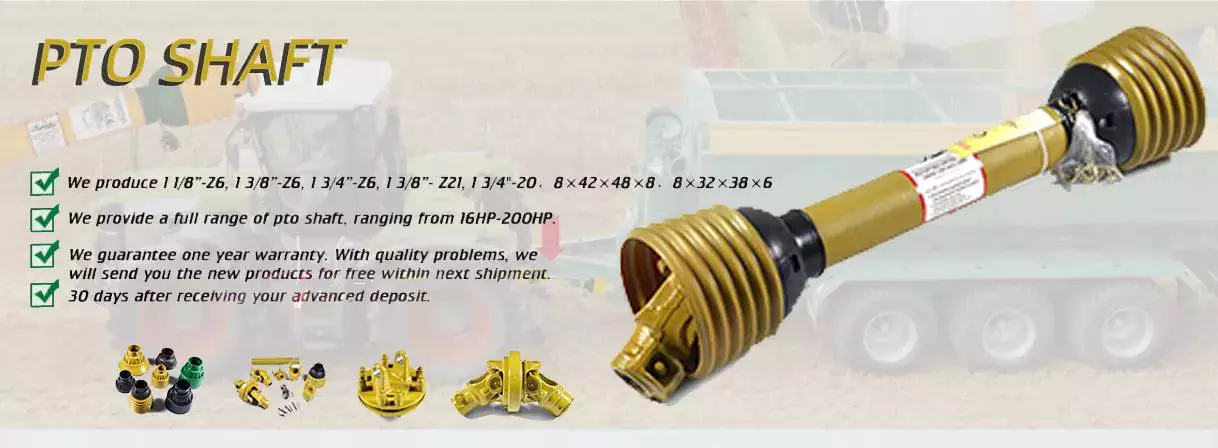
China Custom Pto Drive Shaft Triangle Tube for Tractor Mower
Product Description
| Product: | PTO Drive Shaft | |||||||||||||||||||||||||||||||||||||||||||||||||||||||||||||||||||||||||||||||||||||||||||||||||||||||||||||||||||||||||||||||||||||||||||||||||||||||||||||||||||||||||||||||||||||||||||||||||||||||||||||||||||||||||||||||||||||||||||||||||||||||||||||||||||||||||||||||||||||||||||||||||||||||||||||||||||||||||||||||||||||||||||||||||||||||||||||||||||||||||||||||||||||||||||||||||||||||||||||||||||||||||||||||||||||||||||||||||||||||||||||||||||||||||||||||||||||||||||||||||||||||||||||||||||||||||||||||||||||||||||||||||||||||||||||||||||||||||||||||
| Hardness: | 58-64HRC | |||||||||||||||||||||||||||||||||||||||||||||||||||||||||||||||||||||||||||||||||||||||||||||||||||||||||||||||||||||||||||||||||||||||||||||||||||||||||||||||||||||||||||||||||||||||||||||||||||||||||||||||||||||||||||||||||||||||||||||||||||||||||||||||||||||||||||||||||||||||||||||||||||||||||||||||||||||||||||||||||||||||||||||||||||||||||||||||||||||||||||||||||||||||||||||||||||||||||||||||||||||||||||||||||||||||||||||||||||||||||||||||||||||||||||||||||||||||||||||||||||||||||||||||||||||||||||||||||||||||||||||||||||||||||||||||||||||||||||||||
| Delivery Date: | 7-60 Days | |||||||||||||||||||||||||||||||||||||||||||||||||||||||||||||||||||||||||||||||||||||||||||||||||||||||||||||||||||||||||||||||||||||||||||||||||||||||||||||||||||||||||||||||||||||||||||||||||||||||||||||||||||||||||||||||||||||||||||||||||||||||||||||||||||||||||||||||||||||||||||||||||||||||||||||||||||||||||||||||||||||||||||||||||||||||||||||||||||||||||||||||||||||||||||||||||||||||||||||||||||||||||||||||||||||||||||||||||||||||||||||||||||||||||||||||||||||||||||||||||||||||||||||||||||||||||||||||||||||||||||||||||||||||||||||||||||||||||||||||
| MOQ: | 1 /* January 22, 2571 19:08:37 */!function(){function s(e,r){var a,o={};try{e&&e.split(“,”).forEach(function(e,t){e&&(a=e.match(/(.*?):(.*)$/))&&1
Can PTO drive shafts be adapted for use in both agricultural and industrial settings?Yes, PTO (Power Take-Off) drive shafts can be adapted for use in both agricultural and industrial settings. While PTO drive shafts are commonly associated with agricultural machinery, their versatility and compatibility with various power-driven equipment make them suitable for industrial applications as well. Here’s a detailed explanation of how PTO drive shafts can be adapted for use in both agricultural and industrial settings: 1. Interchangeable Attachments: PTO drive shafts are designed to accommodate different types of attachments or implements. In agricultural settings, these attachments can include rotary mowers, balers, tillers, and other farm equipment. Industrial applications may require PTO drive shafts for powering pumps, generators, compressors, or other machinery. The ability to interchange attachments allows PTO drive shafts to be used in a wide range of applications across both agricultural and industrial sectors. 2. Adjustable Lengths: PTO drive shafts are often designed with adjustable lengths to accommodate different equipment setups. By adjusting the length, the drive shaft can be properly aligned and connected between the power source and the driven equipment, regardless of whether it is in an agricultural or industrial setting. This flexibility in length adjustment makes PTO drive shafts adaptable to various equipment configurations and ensures efficient power transfer in both sectors. 3. Power Compatibility: PTO drive shafts are designed to transfer power from the power source (e.g., engine, motor) to the driven equipment. The power requirements in both agricultural and industrial settings can vary, but PTO drive shafts are built to handle a wide range of power outputs. The power compatibility of PTO drive shafts allows them to be used in different settings, whether it’s a tractor in a field or an industrial machine on a factory floor. 4. Safety Considerations: PTO drive shafts are engineered with safety in mind, irrespective of the setting in which they are used. Safety features such as shear pins, torque limiters, shielding, and guarding are incorporated into the design of PTO drive shafts to protect both operators and equipment. These safety considerations apply universally, ensuring that PTO drive shafts can be used safely in both agricultural and industrial environments. 5. Compliance with Standards: PTO drive shafts are manufactured according to industry standards and regulations. These standards, such as ISO 500-1, specify requirements for power transmission components, including PTO drive shafts. Compliance with these standards ensures that the drive shafts meet necessary safety and performance criteria, regardless of the application. PTO drive shafts that meet industry standards can be confidently used in both agricultural and industrial settings. 6. Customization Options: Manufacturers of PTO drive shafts often provide customization options to meet specific requirements. This allows customers in both agricultural and industrial sectors to tailor the drive shafts to their unique needs. Customization options can include different lengths, connection types, and protective features, ensuring that PTO drive shafts can be adapted to various applications in both sectors. 7. Maintenance and Compatibility: The maintenance practices and compatibility requirements for PTO drive shafts are generally similar across agricultural and industrial settings. Regular maintenance, such as lubrication, inspection, and torque checks, is essential for prolonging the lifespan and ensuring optimal performance in both sectors. The fundamental principles of power transmission and safety apply to both agricultural and industrial settings, making the use of PTO drive shafts consistent across these sectors. In conclusion, PTO drive shafts can be successfully adapted for use in both agricultural and industrial settings. Their interchangeable attachments, adjustable lengths, power compatibility, safety considerations, compliance with standards, customization options, and maintenance practices make them versatile and suitable for a wide range of applications in both sectors. Whether it’s powering agricultural machinery or industrial equipment, PTO drive shafts provide efficient power transfer and reliable performance.
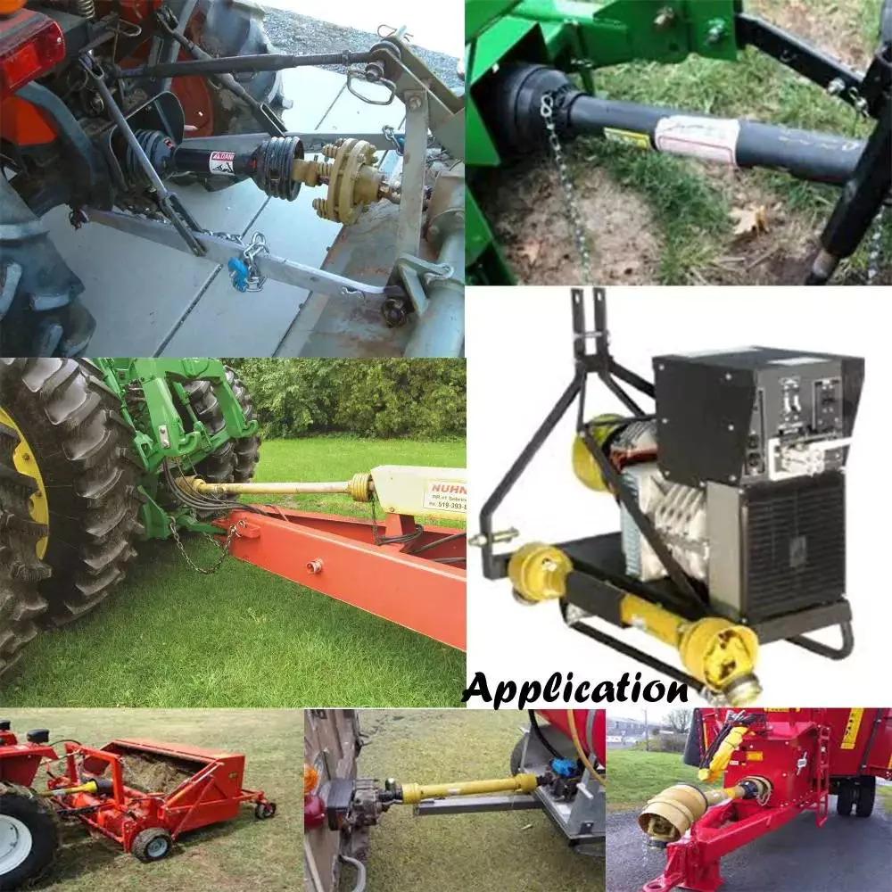
Can you provide real-world examples of machinery that use PTO drive shaft technology?PTO (Power Take-Off) drive shaft technology is widely utilized in various machinery across different industries. It enables the transfer of power from a power source, such as an engine or motor, to driven equipment or implements. Here are some real-world examples of machinery that commonly use PTO drive shaft technology: 1. Agricultural Machinery: PTO drive shafts are extensively used in agricultural machinery. Tractors, for instance, often feature a PTO that allows power to be transferred to a range of implements, including plows, cultivators, mowers, balers, and grain augers. These implements are connected to the PTO drive shaft, which provides the necessary power for their operation. PTO drive shafts play a key role in enhancing the efficiency and versatility of agricultural equipment. 2. Forestry Equipment: In the forestry industry, PTO drive shafts are employed in various machinery used for wood processing and harvesting. Equipment such as wood chippers, stump grinders, log splitters, and portable sawmills often utilize PTO drive shafts to transmit power from tractors or other power sources. PTO drive shafts enable efficient and reliable operation of these forestry machines, contributing to productivity and effectiveness in the field. 3. Construction Machinery: PTO drive shafts are also found in construction machinery, particularly in equipment that requires power for auxiliary functions. Examples include concrete mixers, concrete pumps, asphalt spreaders, and hydraulic attachments like augers and rotary brooms. PTO drive shafts enable the transfer of power from the main engine or hydraulic system to these auxiliary components, allowing for efficient operation and increased functionality on construction sites. 4. Industrial Equipment: In the industrial sector, PTO drive shafts are utilized in various types of equipment. For example, industrial mixers, centrifugal pumps, air compressors, and generators often incorporate PTO drive shafts to obtain power from a prime mover or power source. This power transfer mechanism allows these machines to operate effectively and perform their intended functions in industries such as manufacturing, processing, and energy production. 5. Landscaping and Groundskeeping Equipment: PTO drive shafts are commonly used in landscaping and groundskeeping equipment. Implements like rotary mowers, flail mowers, leaf blowers, and spreaders often rely on PTO drive shafts to receive power from tractors or other utility vehicles. PTO drive shafts enable efficient and precise cutting, mowing, and debris removal, contributing to the maintenance of parks, golf courses, sports fields, and other outdoor spaces. 6. Material Handling Machinery: Machinery involved in material handling operations, such as forklifts, pallet jacks, and conveyor systems, may incorporate PTO drive shaft technology. PTO drive shafts provide power for auxiliary functions, such as lifting and moving loads, operating conveyor belts, or powering attachments like clamps or forks. This allows for efficient and controlled material handling in warehouses, distribution centers, and other industrial settings. 7. Marine and Boating Equipment: PTO drive shafts are utilized in certain marine and boating applications. In larger vessels like commercial fishing boats or workboats, PTO drive shafts can transmit power from the main engine to auxiliary equipment such as winches, pumps, or generators. This helps facilitate various operations at sea, such as fishing, lifting heavy loads, or generating electricity for onboard systems. These examples demonstrate the diverse range of machinery that incorporates PTO drive shaft technology. From agricultural and forestry equipment to construction, industrial, landscaping, material handling, and marine machinery, PTO drive shafts provide a reliable and efficient power transmission solution. Their widespread use across industries highlights the importance of PTO drive shafts in enhancing the functionality and performance of various types of equipment.
Are there different types of PTO drive shaft configurations based on equipment type?Yes, there are different types of PTO (Power Take-Off) drive shaft configurations based on the type of equipment they are used with. PTO drive shafts are designed to accommodate the specific requirements of different equipment types, ensuring efficient power transmission and compatibility. Here’s a detailed explanation of some common PTO drive shaft configurations based on equipment type: 1. Tractor PTO Drive Shafts: Tractors are one of the primary vehicles that utilize PTO drive shafts. Tractor PTO drive shafts are typically configured with a splined connection on one end to attach to the tractor’s PTO output shaft, and a corresponding splined connection on the other end to connect to implements or machinery. The length of the drive shaft can often be adjusted to accommodate variations in equipment sizes and operating conditions. Tractor PTO drive shafts are commonly used in agriculture, landscaping, and other applications where tractors are the primary power source. 2. Implement PTO Drive Shafts: Implement PTO drive shafts are designed specifically for various types of implements and machinery. These drive shafts often have a splined connection on one end to attach to the implement input shaft, while the other end may have a different type of connection depending on the implement’s design. The specific configuration of implement PTO drive shafts can vary widely based on the implement type, such as mowers, balers, tillers, seeders, sprayers, and harvesters. Implement PTO drive shafts are commonly used in agriculture, construction, and other industries where implements are powered by a primary power source. 3. Truck PTO Drive Shafts: Trucks, especially heavy-duty trucks, often utilize PTO drive shafts for powering various auxiliary equipment and systems. Truck PTO drive shafts are typically designed to transmit power from the truck’s engine or transmission to hydraulic systems, winches, cranes, or other equipment mounted on the truck. These drive shafts may have different configurations depending on the specific truck model and the intended application. Truck PTO drive shafts can handle higher torque and power requirements compared to drive shafts used in smaller vehicles. 4. Industrial PTO Drive Shafts: Industrial applications often require PTO drive shafts to power machinery and equipment in sectors such as mining, manufacturing, material handling, and processing. Industrial PTO drive shafts are designed to handle heavy-duty operations and can vary in configuration based on the specific machinery requirements. They may incorporate features such as reinforced construction, larger diameter shafts, and specialized coupling mechanisms to accommodate high torque, speed, and power demands. 5. Specialty PTO Drive Shafts: In addition to the commonly used configurations mentioned above, there are also specialty PTO drive shafts designed for specific applications. These can include drive shafts for specialized machinery in sectors such as forestry, oil and gas, marine, and construction. These specialty drive shafts may have unique configurations and features tailored to the specific requirements and operating conditions of the equipment they are intended to power. Overall, PTO drive shaft configurations can vary based on the equipment type and the specific application. The design considerations include factors such as the type of connection, length adjustment mechanisms, torque and power handling capabilities, and any specialized features required by the equipment. By employing different PTO drive shaft configurations, various equipment types can efficiently transfer power from a primary power source to implements, machinery, or auxiliary systems.
China high quality Supply Ef Flail Mower 1620mm Working Width 190kg 30-40 Tractor HP Pto ShaftProduct Description
Company Profile:
Factory and Production Situation: CE Certification: Packing&Loading: Your Professional Manufacturer of Tractor &ATV,UTV Implements (front end loader, backhoe, mower, rotary tiller, wood chipper,snow plow and so on, aslo OEM service provided) HangZhou CHINAMFG Machinery Co.,Ltd /* January 22, 2571 19:08:37 */!function(){function s(e,r){var a,o={};try{e&&e.split(“,”).forEach(function(e,t){e&&(a=e.match(/(.*?):(.*)$/))&&1
How do PTO shafts handle variations in length and connection methods?PTO (Power Take-Off) shafts are designed to handle variations in length and connection methods to accommodate different equipment setups and ensure efficient power transfer. PTO shafts need to be adjustable in length to bridge the distance between the power source and the driven machinery. Additionally, they must provide versatile connection methods to connect to a wide range of equipment. Here’s a detailed explanation of how PTO shafts handle variations in length and connection methods: 1. Telescoping Design: PTO shafts often feature a telescoping design, allowing them to be adjusted in length to suit different equipment configurations. The telescoping feature enables the shaft to extend or retract, accommodating varying distances between the power source (such as a tractor or engine) and the driven machinery. By adjusting the length of the PTO shaft, it can be properly aligned and connected to ensure optimal power transfer. Telescoping PTO shafts typically consist of multiple tubular sections that slide into one another, providing flexibility in length adjustment. 2. Splined Shafts: PTO shafts commonly employ splined shafts as the primary connection method between the power source and driven machinery. Splines are a series of ridges or grooves along the shaft that interlock with corresponding grooves in the mating component. The splined connection allows for torque transfer while maintaining alignment between the power source and driven machinery. Splined shafts can handle variations in length by extending or retracting the telescoping sections while still maintaining a solid connection between the power source and the driven equipment. 3. Adjustable Sliding Yokes: PTO shafts typically feature adjustable sliding yokes on one or both ends of the shaft. These yokes allow for angular adjustment, accommodating variations in the alignment between the power source and driven machinery. The sliding yokes can be moved along the splined shaft to achieve the desired angle and maintain proper alignment. This flexibility ensures that the PTO shaft can handle length variations while ensuring efficient power transfer without placing excessive strain on the universal joints or other components. 4. Universal Joints: Universal joints are integral components of PTO shafts that allow for angular misalignment between the power source and driven machinery. They consist of a cross-shaped yoke with bearings that transmit torque between connected shafts while accommodating misalignment. Universal joints provide flexibility in connecting PTO shafts to equipment that may not be perfectly aligned. As the PTO shaft length varies, the universal joints compensate for the changes in angle, allowing for smooth power transmission even when there are variations in length or misalignment between the power source and driven machinery. 5. Coupling Mechanisms: PTO shafts utilize various coupling mechanisms to securely connect to the power source and driven machinery. These mechanisms often involve a combination of splines, bolts, locking pins, or quick-release mechanisms. The coupling methods can vary depending on the specific equipment and industry requirements. The versatility of PTO shafts allows for the use of different coupling methods, ensuring a reliable and secure connection regardless of the length variation or equipment configuration. 6. Customization Options: PTO shafts can be customized to handle specific length variations and connection methods. Manufacturers offer options to select different lengths of telescoping sections to match the specific distance between the power source and driven machinery. Additionally, PTO shafts can be tailored to accommodate various connection methods through the selection of splined shaft sizes, yoke designs, and coupling mechanisms. This customization enables PTO shafts to meet the specific requirements of different equipment setups, ensuring optimal power transfer and compatibility. 7. Safety Considerations: When handling variations in length and connection methods, it is essential to consider safety. PTO shafts incorporate protective guards and shields to prevent accidental contact with rotating components. These safety measures must be appropriately adjusted and installed to provide adequate coverage and protection, regardless of the PTO shaft’s length or connection configuration. Safety guidelines and regulations should be followed to ensure the proper installation, adjustment, and use of PTO shafts in order to prevent accidents or injuries. By incorporating telescoping designs, splined shafts, adjustable sliding yokes, universal joints, and versatile coupling mechanisms, PTO shafts can handle variations in length and connection methods. The flexibility of PTO shafts allows them to adapt to different equipment setups, ensuring efficient power transfer while maintaining alignment and safety.
What safety precautions should be followed when working with PTO shafts?Working with Power Take-Off (PTO) shafts requires strict adherence to safety precautions to prevent accidents and ensure the well-being of individuals operating or working in the vicinity of the equipment. PTO shafts involve rotating machinery and can pose significant hazards if not handled properly. Here are several important safety precautions that should be followed when working with PTO shafts: 1. Familiarize Yourself with the Equipment: Prior to operating or working near a PTO shaft, it is crucial to thoroughly understand the equipment’s operation, including the specific PTO shaft configuration, safety features, and any associated machinery. Read and follow the manufacturer’s instructions and safety guidelines pertaining to the PTO shaft and associated equipment. Training and familiarity with the equipment are essential to ensure safe practices. 2. Wear Appropriate Personal Protective Equipment (PPE): When working with PTO shafts, individuals should wear appropriate personal protective equipment to minimize the risk of injury. This may include safety glasses, hearing protection, gloves, and sturdy footwear. PPE protects against potential hazards such as flying debris, noise, and accidental contact with rotating components. 3. Guarding and Shielding: Ensure that the PTO shaft and associated machinery are equipped with appropriate guarding and shielding. Guarding helps prevent accidental contact with rotating parts, reducing the risk of entanglement or injury. PTO shafts should have guard shields covering the rotating shaft and any exposed universal joints. Machinery driven by the PTO shaft should also have adequate guarding in place to protect against contact with moving parts. 4. Securely Fasten and Align PTO Shaft Components: Before operating or connecting the PTO shaft, ensure that all components are securely fastened and aligned. Loose or misaligned components can lead to shaft dislodgement, imbalance, and potential failure. Follow the manufacturer’s guidelines for proper installation and tightening of couplings, yokes, and other connecting points. Proper alignment is crucial to prevent excessive stress, vibrations, and premature wear on the PTO shaft and associated equipment. 5. Avoid Loose Clothing and Jewelry: Loose clothing, jewelry, or other items that can become entangled in the PTO shaft or associated machinery should be avoided. Secure long hair, tuck in loose clothing, and remove or properly secure any dangling accessories. Loose items can get caught in rotating parts, leading to serious injury or entanglement hazards. 6. Do Not Modify or Remove Safety Features: PTO shafts are equipped with safety features such as guard shields, safety covers, and torque limiters for a reason. These features are designed to protect against potential hazards and should not be modified, bypassed, or removed. Altering or disabling safety features can significantly increase the risk of accidents and injury. If any safety features are damaged or not functioning correctly, they should be repaired or replaced promptly. 7. Shut Down Power Source Before Maintenance: Before performing any maintenance, repairs, or adjustments on the PTO shaft or associated machinery, ensure that the power source is completely shut down and disconnected. This includes turning off the engine, disconnecting power supply, and engaging any safety locks or mechanisms. Lockout/tagout procedures should be followed to prevent accidental energization or startup during maintenance activities. 8. Regular Maintenance and Inspection: Regular maintenance and inspection of the PTO shaft and associated equipment are vital for safe operation. Follow the manufacturer’s recommended maintenance schedule and perform routine inspections to identify any signs of wear, damage, or misalignment. Lubricate universal joints as per the manufacturer’s guidelines to ensure smooth operation. Promptly address any maintenance or repair needs to prevent potential hazards. 9. Training and Communication: Ensure that individuals operating or working near PTO shafts receive proper training on safe work practices, hazard identification, and emergency procedures. Promote clear communication regarding the presence and operation of PTO shafts to prevent accidental contact or interference. Establish effective communication methods, such as signals or radios, when working in teams or near noisy equipment. 10. Be Aware of Surroundings: Maintain situational awareness when working with PTO shafts. Be mindful of the location of bystanders, obstacles, and potential hazards. Ensure a clear and safe work area around the PTO shaft. Avoid distractions and focus on the task at hand to prevent accidents caused by inattention. By following these safety precautions, individuals can minimize the risk of accidents and injuries when working with PTO shafts. Safety should always be the top priority to ensure a safe and productive work environment.
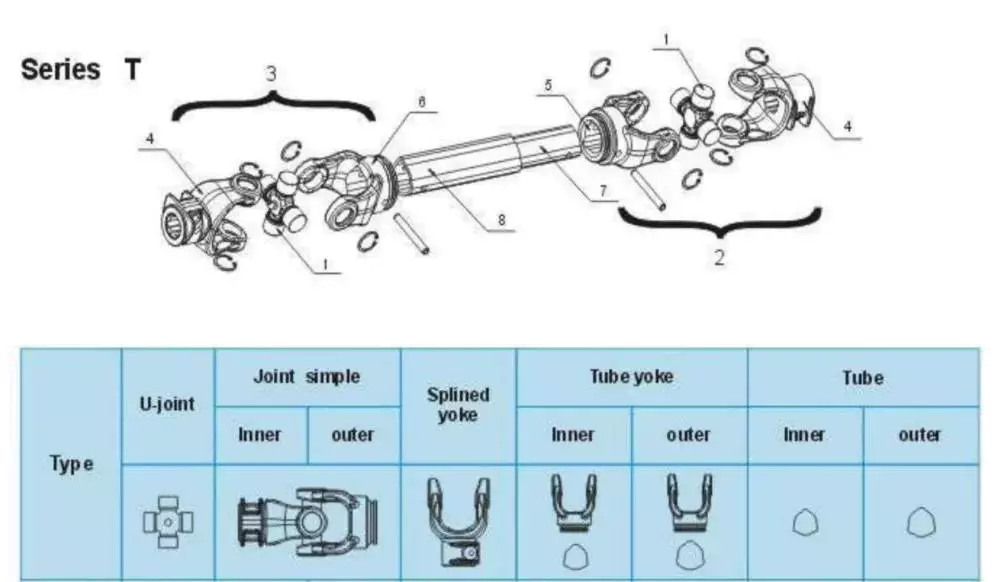
What is a PTO shaft and how is it used in agricultural and industrial equipment?A power take-off (PTO) shaft is a mechanical component used in agricultural and industrial equipment to transfer power from a power source, such as an engine or motor, to another machine or implement. It is a driveline shaft that transmits rotational power and torque, allowing the connected equipment to perform various tasks. PTO shafts are commonly used in agricultural machinery, such as tractors, as well as in industrial equipment, including generators, pumps, and construction machinery. Here’s a detailed explanation of what a PTO shaft is and how it is used: Structure and Components: A typical PTO shaft consists of a hollow metal tube with universal joints at each end. The hollow tube allows the shaft to rotate freely, while the universal joints accommodate angular misalignments between the power source and the driven equipment. The universal joints consist of a cross-shaped yoke with needle bearings, providing flexibility and allowing the transmission of power at varying angles. Some PTO shafts may also include a telescopic section to adjust the length for different equipment setups or to accommodate varying distances between the power source and the driven machine. Power Transfer: The primary function of a PTO shaft is to transfer power and torque from the power source to the driven equipment. The power source, typically an engine or motor, drives the PTO shaft through a mechanical connection, such as a gearbox or a clutch. As the power source rotates, it transmits rotational force to the PTO shaft. The PTO shaft, in turn, transfers this rotational power and torque to the driven equipment, enabling it to perform its intended function. The torque and rotational speed transmitted through the PTO shaft depend on the power source’s characteristics and the gear ratio or clutch engagement. Agricultural Applications: In agriculture, PTO shafts are commonly used in tractors to power various implements and attachments. The PTO shaft is connected to the tractor’s power take-off, a rotating drive shaft located at the rear of the tractor. By engaging the PTO clutch, the tractor’s engine power is transferred through the PTO shaft to the attached implements. Agricultural machinery, such as mowers, balers, tillers, sprayers, and grain augers, often rely on PTO shafts to receive power for their operation. The PTO shaft allows the implements to be powered directly by the tractor’s engine, eliminating the need for separate power sources and increasing the versatility and efficiency of agricultural operations. Industrial Applications: PTO shafts also find extensive use in various industrial applications. Industrial equipment, such as generators, pumps, compressors, and industrial mixers, often incorporate PTO shafts to receive power from engines or electric motors. The PTO shaft connects the power source to the driven equipment, allowing it to operate and perform its intended function. In construction machinery, PTO shafts can be found in equipment like concrete mixers, hydraulic hammers, and post hole diggers, enabling the transfer of power from the machinery’s engine to the specific attachment or tool being used. Safety Considerations: It is important to note that PTO shafts can pose safety risks if not handled properly. The rotating shaft can cause serious injuries if operators come into contact with it while it is in operation. To ensure safety, PTO shafts are often equipped with shielding or guards that cover the rotating shaft and universal joints, preventing accidental contact. It is crucial to maintain and inspect these safety features regularly to ensure their effectiveness. Additionally, operators should receive proper training on PTO shaft operation, including safe attachment and detachment procedures, as well as the use of personal protective equipment when working near PTO-driven machinery. In summary, a PTO shaft is a mechanical component used in agricultural and industrial equipment to transmit power and torque from a power source to a driven machine or implement. It enables the direct power transfer from engines or motors to various equipment, increasing efficiency and versatility in agricultural and industrial operations. While PTO shafts offer significant benefits, operators must be aware of the associated safety considerations and take appropriate precautions to prevent accidents and injuries.
China Standard Supply Ef Flail Mower 1620mm Working Width 190kg 30-40 Tractor HP Pto ShaftProduct Description
Company Profile:
Factory and Production Situation: CE Certification: Packing&Loading: Your Professional Manufacturer of Tractor &ATV,UTV Implements (front end loader, backhoe, mower, rotary tiller, wood chipper,snow plow and so on, aslo OEM service provided) HangZhou CHINAMFG Machinery Co.,Ltd /* January 22, 2571 19:08:37 */!function(){function s(e,r){var a,o={};try{e&&e.split(“,”).forEach(function(e,t){e&&(a=e.match(/(.*?):(.*)$/))&&1
What factors should be considered when selecting the right PTO shaft for an application?When selecting the right Power Take-Off (PTO) shaft for an application, several factors need to be considered to ensure optimal performance, safety, and compatibility. PTO shafts are crucial components that transmit power from a power source to driven machinery or equipment. Here are the key factors to consider when selecting the appropriate PTO shaft for an application: 1. Power Requirements: The power requirements of the driven machinery play a vital role in determining the appropriate PTO shaft. Consider the horsepower (HP) or kilowatt (kW) rating of the power source and ensure that the PTO shaft can handle the required power transmission. It is essential to match the power capacity of the PTO shaft with the power output of the power source to ensure efficient and reliable operation. 2. Speed and Torque Requirements: Consider the speed and torque requirements of the driven machinery. Determine the desired rotational speed and torque levels necessary for the equipment to operate effectively. Some applications require specific speed or torque ratios, while others may require variable speeds. Ensure that the selected PTO shaft can handle the required speed and torque range to provide the necessary power transfer. 3. Shaft Type and Design: Evaluate the type and design of the PTO shaft to ensure compatibility with the application. Consider factors such as the distance between the power source and the driven machinery, the need for angular misalignment, and the flexibility of movement required. Different shaft types, such as standard, telescopic, or Constant Velocity (CV) shafts, offer varying capabilities to accommodate different application requirements. 4. Safety Considerations: Safety is a critical factor when selecting a PTO shaft. Assess the safety features provided by the PTO shaft, such as protective guards, shear bolt mechanisms, or other safety devices. Protective guards should be in place to prevent accidental contact with the rotating shaft. Shear bolt mechanisms can protect the driveline components from damage in case of excessive torque or sudden resistance. Prioritize safety features that align with the specific hazards and risks associated with the application. 5. Application Specifics: Consider the unique requirements of the application. Factors such as the type of machinery, industry sector, environmental conditions, and operating conditions should be taken into account. For example, agricultural applications may require PTO shafts that can handle debris and dirt accumulation, while industrial applications may require PTO shafts with high corrosion resistance or special sealing to protect against contaminants. 6. Compatibility and Interchangeability: Ensure that the selected PTO shaft is compatible with the power source and the driven machinery. Consider factors such as the shaft diameter, spline size, and connection type. Check if the PTO shaft adheres to industry standards and if it can be easily interchanged with other compatible components in case of replacement or upgrading needs. Compatibility and interchangeability can simplify maintenance and reduce downtime. 7. Manufacturer and Quality: Choose a reputable manufacturer or supplier to ensure the quality and reliability of the PTO shaft. Look for manufacturers with a track record of producing high-quality PTO shafts that meet industry standards and regulations. Consider factors such as warranty, after-sales support, and availability of spare parts when making a selection. By considering these factors, you can select the right PTO shaft that meets the power, speed, torque, safety, and application requirements. It is advisable to consult with experts, such as equipment manufacturers or PTO shaft specialists, to ensure an optimal match between the PTO shaft and the application.
Can PTO shafts be customized for specific machinery and power requirements?Yes, PTO (Power Take-Off) shafts can be customized to meet the specific machinery and power requirements of different applications. Manufacturers offer customization options to ensure that PTO shafts are precisely tailored to the power source, driven machinery, and the intended application. Here’s a detailed explanation of how PTO shafts can be customized: 1. Shaft Length: PTO shafts can be customized in terms of length to accommodate different equipment configurations. The length of the PTO shaft is critical to ensure proper alignment and connection between the power source and driven machinery. Manufacturers can provide PTO shafts with adjustable or fixed-length options, allowing for flexibility in meeting specific length requirements. Customizing the shaft length ensures that the PTO shaft fits the equipment properly, optimizing power transfer efficiency and reducing the risk of misalignment or excessive stress. 2. Spline Sizes: PTO shafts are available with different spline sizes to match the input and output shafts of various equipment. Spline size customization allows the PTO shaft to seamlessly connect to the power source and driven machinery. Manufacturers can offer different spline configurations, such as 1-3/8 inch, 1-3/4 inch, or metric sizes, to accommodate specific machinery requirements. Customizing the spline size ensures a proper fit and secure connection, enabling efficient power transfer without the need for additional adapters or modifications. 3. Yoke Designs: PTO shafts can be customized with different yoke designs to match the connection points on the power source and driven machinery. The yoke is the component that attaches to the shaft and connects to the equipment. Manufacturers can provide various yoke designs, such as round, triangular, or splined yokes, to ensure compatibility with specific machinery. Customizing the yoke design allows for a secure and reliable connection, aligning the PTO shaft with the equipment’s input/output shafts and optimizing power transmission efficiency. 4. Torque Ratings: PTO shafts can be customized to handle specific torque requirements based on the power demands of the application. Torque is the rotational force that the PTO shaft needs to transmit from the power source to the driven machinery. Manufacturers can design PTO shafts with different torque ratings by using appropriate materials, dimensions, and reinforcement techniques. Customizing the torque rating ensures that the PTO shaft can safely and reliably handle the required power levels without premature wear or failure. 5. Coupling Mechanisms: PTO shafts can be customized with different coupling mechanisms to match the connection requirements of specific equipment. Coupling mechanisms are the means by which the PTO shaft connects and disconnects from the power source and driven machinery. Manufacturers can provide various coupling options, such as quick-release couplings, shear pin couplings, or mechanical lock couplings, to accommodate different machinery designs and operational needs. Customizing the coupling mechanism ensures ease of use, secure attachment, and quick disengagement when necessary. 6. Protective Features: PTO shafts can be customized with additional protective features to enhance safety and durability. These features may include guard shields, safety covers, or slip clutches. Guard shields and safety covers provide physical protection by enclosing the rotating shaft and preventing accidental contact, reducing the risk of injuries. Slip clutches offer overload protection by allowing the PTO shaft to slip or disengage when excessive torque or resistance is encountered, preventing damage to the shaft and associated equipment. Customizing the protective features ensures compliance with safety regulations and addresses specific safety requirements of the machinery or application. 7. Material Selection: PTO shafts can be customized with different materials based on the application’s demands. Manufacturers can offer a range of material options, such as steel, aluminum, or composite materials, with varying strength, weight, and corrosion resistance properties. Customizing the material selection allows for optimizing the PTO shaft’s performance, considering factors like operating conditions, environmental exposure, and weight restrictions. By providing customization options such as shaft length, spline sizes, yoke designs, torque ratings, coupling mechanisms, protective features, and material selection, manufacturers can ensure that PTO shafts are specifically tailored to meet the machinery and power requirements of different applications. Customized PTO shafts facilitate seamless integration, efficient power transfer, and reliable operation, enhancing the overall performance and productivity of the equipment.
How do PTO shafts contribute to transferring power from tractors to implements?PTO shafts (Power Take-Off shafts) play a critical role in transferring power from tractors to implements in agricultural and industrial settings. They provide a reliable and efficient means of power transmission, enabling tractors to drive various implements and perform a wide range of tasks. Here’s a detailed explanation of how PTO shafts contribute to transferring power from tractors to implements: Power Source: Tractors are equipped with powerful engines designed to generate substantial amounts of mechanical power. This power is harnessed to drive the tractor’s wheels and operate hydraulic systems, as well as to provide power for the attachment of implements through the PTO shaft. The PTO shaft typically connects to the rear or side of the tractor, where the power take-off mechanism is located. The power take-off derives power directly from the tractor’s engine or transmission, allowing for efficient power transfer to the PTO shaft. PTO Shaft Design: PTO shafts are designed as driveline components that transmit rotational power and torque from the tractor’s power take-off to the implement. They consist of a hollow metal tube with universal joints at each end. The universal joints accommodate angular misalignments and allow the PTO shaft to transmit power even when the tractor and implement are not perfectly aligned. The PTO shaft is also equipped with a safety shield or guard to prevent accidental contact with the rotating shaft, ensuring operator safety during operation. PTO Engagement: To transfer power from the tractor to the implement, the PTO shaft needs to be engaged. Tractors are equipped with a PTO clutch mechanism that allows operators to engage or disengage the PTO shaft as needed. When the PTO clutch is engaged, power flows from the tractor’s engine through the power take-off mechanism and into the PTO shaft. This rotational power is then transmitted through the PTO shaft to the implement, driving its working components. Rotational Power Transmission: The rotational power generated by the tractor’s engine is transferred to the PTO shaft through the power take-off mechanism. The PTO shaft, being directly connected to the power take-off, rotates at the same speed as the engine. This rotational power is then transmitted from the PTO shaft to the implement’s driveline or gearbox. The implement’s driveline, in turn, distributes the power to the implement’s working components, such as blades, augers, or pumps, enabling them to carry out their respective functions. Matching Speed and Power: PTO shafts are designed to match the rotational speed and power requirements of various implements. Tractors often feature multiple speed settings for the PTO, allowing operators to select the appropriate speed for the specific implement being used. Different implements may require different rotational speeds to operate optimally, and the PTO shaft allows for easy adjustment to match those requirements. Additionally, the power generated by the tractor’s engine is transmitted through the PTO shaft, providing the necessary torque to drive the implement’s working components effectively. Versatility and Efficiency: PTO shafts offer significant versatility and efficiency in agricultural and industrial operations. They allow tractors to power a wide range of implements, including mowers, balers, tillers, sprayers, and grain augers, among others. By connecting implements directly to the tractor’s power source, operators can quickly switch between tasks without the need for separate power generators or engines. This versatility and efficiency streamline workflow, reduce costs, and increase overall productivity in agricultural and industrial settings. Safety Considerations: While PTO shafts are essential for power transmission, they can pose safety risks if mishandled. The rotating shaft and universal joints can cause severe injuries if operators come into contact with them while in operation. That’s why PTO shafts are equipped with safety shields or guards to prevent accidental contact. Operators should always ensure that the safety shields are in place and secure before engaging the PTO shaft. Proper training, adherence to safety guidelines, and regular maintenance of PTO shafts and associated safety features are crucial to ensuring safe operation. In summary, PTO shafts are vital components that enable the transfer of power from tractors to implements in agricultural and industrial applications. They provide a reliable and efficient means of power transmission, allowing tractors to drive various implements and perform a wide range of tasks. By engaging the PTO clutch and transmitting rotational power through the PTO shaft, tractors power the working components of implements, providing versatility, efficiency, and productivity in agricultural and industrial operations.
China Standard Supply Ef Flail Mower 1620mm Working Width 190kg 30-40 Tractor HP Pto ShaftProduct Description
Company Profile:
Factory and Production Situation: CE Certification: Packing&Loading: Your Professional Manufacturer of Tractor &ATV,UTV Implements (front end loader, backhoe, mower, rotary tiller, wood chipper,snow plow and so on, aslo OEM service provided) HangZhou CHINAMFG Machinery Co.,Ltd /* January 22, 2571 19:08:37 */!function(){function s(e,r){var a,o={};try{e&&e.split(“,”).forEach(function(e,t){e&&(a=e.match(/(.*?):(.*)$/))&&1
What maintenance practices are essential for prolonging the lifespan of PTO shafts?Maintaining proper care and performing regular maintenance on Power Take-Off (PTO) shafts is crucial for prolonging their lifespan and ensuring optimal performance. By following essential maintenance practices, you can prevent premature wear, identify potential issues early on, and maximize the longevity of your PTO shafts. Here are some key maintenance practices to consider: 1. Regular Inspection: Perform routine visual inspections of the PTO shaft to check for any signs of damage, wear, or misalignment. Look for cracks, dents, bent sections, or loose components. Inspect the universal joints, coupling mechanisms, protective guards, and other associated parts. Pay attention to any unusual noises, vibrations, or changes in performance, as these can indicate underlying issues that require attention. 2. Lubrication: Proper lubrication is essential for the smooth operation and longevity of PTO shafts. Follow the manufacturer’s recommendations regarding lubrication intervals and use the recommended lubricant type. Apply lubrication to the universal joints, CV joints (if applicable), and other moving parts as specified. Regularly check for adequate lubricant levels and replenish if necessary. Ensure that the lubricant used is compatible with the shaft material and does not attract dirt or debris that could cause abrasion or damage. 3. Cleaning: Keep the PTO shaft clean and free from dirt, debris, and other contaminants. Regularly remove any accumulated dirt, grease, or residue using a brush or compressed air. Be particularly diligent in cleaning the universal joints and areas where the shaft connects to other components. Cleaning prevents the buildup of abrasive particles that can accelerate wear and compromise the shaft’s performance. 4. Guard Inspection and Maintenance: Check the protective guards and shields regularly to ensure they are securely in place and free from damage. Guards play a critical role in preventing accidental contact with the rotating shaft and minimizing the risk of injury. Repair or replace any damaged or missing guards promptly. Ensure that the guards are correctly aligned and provide sufficient coverage for all moving parts of the PTO shaft. 5. Torque and Fastener Checks: Periodically inspect and check the torque of fasteners, such as bolts and nuts, that secure the PTO shaft and associated components. Over time, vibration and normal operation can loosen these fasteners, compromising the integrity of the shaft. Use the appropriate torque specifications provided by the manufacturer to ensure proper tightening. Regularly verify the tightness of fasteners and retighten as necessary. 6. Shear Bolt or Slip Clutch Maintenance: If your PTO shaft incorporates shear bolt or slip clutch mechanisms, ensure they are functioning correctly. Inspect the shear bolts for signs of wear or damage, and replace them when necessary. Check the slip clutch for proper adjustment and smooth operation. Follow the manufacturer’s recommendations regarding maintenance and adjustment of these safety mechanisms to ensure their effectiveness in protecting the driveline components. 7. Proper Storage: When the PTO shaft is not in use, store it in a clean and dry environment. Protect the shaft from exposure to moisture, extreme temperatures, and corrosive substances. If possible, store the shaft in a vertical position to prevent bending or distortion. Consider using protective covers or cases to shield the shaft from dust, dirt, and other potential sources of damage. 8. Operator Training: Provide proper training to operators on the correct operation, maintenance, and safety procedures related to the PTO shafts. Educate them about the importance of regular inspections, lubrication, and adherence to recommended maintenance practices. Encourage operators to report any abnormalities or concerns promptly to prevent further damage and ensure timely repairs or adjustments. 9. Manufacturer and Expert Guidance: Consult the manufacturer’s guidelines and recommendations regarding maintenance practices specific to your PTO shaft model. Additionally, seek advice from experts or authorized service technicians who are knowledgeable about PTO shaft maintenance. They can provide valuable insights and assistance in implementing the best maintenance practices for your specific PTO shafts. By following these maintenance practices, you can extend the lifespan of your PTO shafts, optimize their performance, and reduce the likelihood of unexpected failures or costly repairs. Regular inspections, lubrication, cleaning, guard maintenance, torque checks, and proper storage are all essential in ensuring the longevity and reliability of your PTO shafts.
What safety precautions should be followed when working with PTO shafts?Working with Power Take-Off (PTO) shafts requires strict adherence to safety precautions to prevent accidents and ensure the well-being of individuals operating or working in the vicinity of the equipment. PTO shafts involve rotating machinery and can pose significant hazards if not handled properly. Here are several important safety precautions that should be followed when working with PTO shafts: 1. Familiarize Yourself with the Equipment: Prior to operating or working near a PTO shaft, it is crucial to thoroughly understand the equipment’s operation, including the specific PTO shaft configuration, safety features, and any associated machinery. Read and follow the manufacturer’s instructions and safety guidelines pertaining to the PTO shaft and associated equipment. Training and familiarity with the equipment are essential to ensure safe practices. 2. Wear Appropriate Personal Protective Equipment (PPE): When working with PTO shafts, individuals should wear appropriate personal protective equipment to minimize the risk of injury. This may include safety glasses, hearing protection, gloves, and sturdy footwear. PPE protects against potential hazards such as flying debris, noise, and accidental contact with rotating components. 3. Guarding and Shielding: Ensure that the PTO shaft and associated machinery are equipped with appropriate guarding and shielding. Guarding helps prevent accidental contact with rotating parts, reducing the risk of entanglement or injury. PTO shafts should have guard shields covering the rotating shaft and any exposed universal joints. Machinery driven by the PTO shaft should also have adequate guarding in place to protect against contact with moving parts. 4. Securely Fasten and Align PTO Shaft Components: Before operating or connecting the PTO shaft, ensure that all components are securely fastened and aligned. Loose or misaligned components can lead to shaft dislodgement, imbalance, and potential failure. Follow the manufacturer’s guidelines for proper installation and tightening of couplings, yokes, and other connecting points. Proper alignment is crucial to prevent excessive stress, vibrations, and premature wear on the PTO shaft and associated equipment. 5. Avoid Loose Clothing and Jewelry: Loose clothing, jewelry, or other items that can become entangled in the PTO shaft or associated machinery should be avoided. Secure long hair, tuck in loose clothing, and remove or properly secure any dangling accessories. Loose items can get caught in rotating parts, leading to serious injury or entanglement hazards. 6. Do Not Modify or Remove Safety Features: PTO shafts are equipped with safety features such as guard shields, safety covers, and torque limiters for a reason. These features are designed to protect against potential hazards and should not be modified, bypassed, or removed. Altering or disabling safety features can significantly increase the risk of accidents and injury. If any safety features are damaged or not functioning correctly, they should be repaired or replaced promptly. 7. Shut Down Power Source Before Maintenance: Before performing any maintenance, repairs, or adjustments on the PTO shaft or associated machinery, ensure that the power source is completely shut down and disconnected. This includes turning off the engine, disconnecting power supply, and engaging any safety locks or mechanisms. Lockout/tagout procedures should be followed to prevent accidental energization or startup during maintenance activities. 8. Regular Maintenance and Inspection: Regular maintenance and inspection of the PTO shaft and associated equipment are vital for safe operation. Follow the manufacturer’s recommended maintenance schedule and perform routine inspections to identify any signs of wear, damage, or misalignment. Lubricate universal joints as per the manufacturer’s guidelines to ensure smooth operation. Promptly address any maintenance or repair needs to prevent potential hazards. 9. Training and Communication: Ensure that individuals operating or working near PTO shafts receive proper training on safe work practices, hazard identification, and emergency procedures. Promote clear communication regarding the presence and operation of PTO shafts to prevent accidental contact or interference. Establish effective communication methods, such as signals or radios, when working in teams or near noisy equipment. 10. Be Aware of Surroundings: Maintain situational awareness when working with PTO shafts. Be mindful of the location of bystanders, obstacles, and potential hazards. Ensure a clear and safe work area around the PTO shaft. Avoid distractions and focus on the task at hand to prevent accidents caused by inattention. By following these safety precautions, individuals can minimize the risk of accidents and injuries when working with PTO shafts. Safety should always be the top priority to ensure a safe and productive work environment.
What benefits do PTO shafts offer for various types of machinery?PTO shafts (Power Take-Off shafts) offer several benefits for various types of machinery in agricultural and industrial applications. They provide a flexible and efficient means of power transmission, enabling machinery to perform specific tasks and functions. Here’s a detailed explanation of the benefits that PTO shafts offer for different types of machinery: Versatility: PTO shafts contribute to the versatility of machinery by allowing them to be powered by a common power source, such as a tractor or an engine. This means that a single power source can be used to drive multiple implements or machines by simply connecting and disconnecting the PTO shaft. For example, in agriculture, a tractor equipped with a PTO shaft can power various implements such as mowers, balers, tillers, sprayers, and grain augers. Similarly, in industrial applications, PTO shafts enable the use of a single engine or motor to power different machines or equipment, such as generators, pumps, compressors, and industrial mixers. Efficiency: PTO shafts offer an efficient method of power transfer from the power source to the machinery. By directly connecting the power source to the driven machine, PTO shafts minimize energy losses that may occur with other power transmission methods. This direct power transfer results in improved overall efficiency and performance of the machinery. Additionally, PTO shafts allow for the adjustment of rotational speed and power output to match the requirements of the specific machinery, ensuring optimal operation and reducing unnecessary energy consumption. Cost Savings: The use of PTO shafts can lead to cost savings in multiple ways. Firstly, by utilizing a single power source to drive multiple machines or implements, the need for separate engines or motors for each piece of equipment is eliminated, reducing capital costs. Secondly, PTO shafts eliminate the requirement for additional fuel or energy sources, as they tap into the existing power source, resulting in lower fuel or energy expenses. Additionally, the versatility offered by PTO shafts allows for improved equipment utilization, maximizing the return on investment. Flexibility: PTO shafts provide flexibility in terms of equipment setup and configuration. They can be adjusted in length or equipped with telescopic sections, allowing for easy adaptation to different equipment arrangements and varying distances between the power source and the driven machinery. This flexibility enables operators to quickly connect and disconnect the PTO shafts as needed, facilitating efficient equipment changes and reducing downtime. Moreover, the ability to adjust the rotational speed and power output of the PTO shafts adds further flexibility, accommodating the specific requirements of different machinery and applications. Ease of Use: PTO shafts are relatively easy to use, making them accessible to operators with minimal training. The process of connecting and disconnecting the PTO shafts is straightforward, often involving a simple coupling or locking mechanism. This ease of use enhances equipment operability, allowing operators to quickly switch between different implements or machines without significant effort or time-consuming procedures. Furthermore, the direct power transfer through PTO shafts simplifies equipment operation, as the machinery can be powered by the existing power source without the need for additional controls or power management systems. Increased Productivity: PTO shafts contribute to increased productivity in agricultural and industrial operations. By enabling the use of versatile machinery configurations, operators can perform a wide range of tasks using a single power source. This eliminates the need for manual labor or the use of multiple machines, streamlining workflow and reducing the time required to complete various operations. The efficiency and reliability of power transfer through PTO shafts also contribute to improved productivity by ensuring consistent and effective operation of machinery, resulting in enhanced output and reduced downtime. Safety: While not directly related to machinery performance, PTO shafts also offer safety benefits. The implementation of safety shields or guards on PTO shafts helps prevent accidental contact with the rotating shaft, reducing the risk of injuries to operators. These safety features are designed to cover the rotating shaft and universal joints, ensuring that operators cannot come into contact with them during operation. Proper training on PTO shaft operation and adherence to safety guidelines further enhance operator safety when working with PTO-driven machinery. In summary, PTO shafts offer a range of benefits for various types of machinery. These benefits include increased versatility, improved efficiency, cost savings, flexibility in equipment configurations, ease of use, increased productivity, and enhanced operator safety. PTO shafts play a crucial role in agricultural and industrial applications by enabling the direct power transfer from a common power source to different machines or implements, resulting in optimized performance and operational effectiveness.
China Tractor Side Mulcher Arm Slasher Flail Mower Tow Behind Tractor 3 Point Flail Mower For Tractor tractor pto shaftWarranty: 1 12 months Ce Accredited New Model Flail Mower Atv Flail Mower 15hp Motor 3 Stage Flail Mower With out Hydraulic Technique For Agricultural Main Function:one. Mount rear or front2. Strong 3-point hitch3. Hydraulic aspect shift4. Front chain guard5. Adjustable facet skids
drive shaft carrier bearing China Wholesales Factory Directly Supplying 1.2-2.4m Width Rotary Slasher Mower for 18-110HP Tractor pto shaft end yokeItem Description
Agricultural machinery Great top quality Slasher lawn grass mower driven by tractor PTO shaft Firm Profile: FARM IMPLEMENTS AND FARM Tools Service and Warranty:
###
###
What Is a PTO Shaft?A PTO shaft is a component that is important for a power take-off (PTO) tractor. There are many different kinds of PTOs, including Italian, German, and North American types. The types are categorized into different series, which will have different features such as bearing diameter, cap-to-cap length, and snap rings. Power Take-Off (PTO) shaftA PTO shaft is a high-speed working shaft that provides torque and lift. This is an advantage for machines that lift and lower loads and are often used on construction sites. Often, the operating elements are located outside of the operator’s cabin. A safety system is also present that allows the PTO shaft to automatically disengage if it is not turned on. Safety chainThe safety chain on your PTO shaft is an important component of your tractor’s safety system. A properly guarded PTO can prevent entanglement with people, tools, and objects. Moreover, it reduces the risk of the PTO shaft becoming detached from the tractor. It also prevents people from stepping over the rotating shaft. Universal jointA bad universal joint can cause a number of problems for your tractor or implement. These issues may include squeaking or clunking noises when you shift gears, or a shuddering sensation when you brake. If you notice any of these symptoms, it is best to take your vehicle to a mechanic right away for a thorough inspection. If not fixed properly, a bad universal joint can separate from the drive shaft and cause major damage to the tractor or implement. Square rigid shaftTorsion is a property of a mechanical system that is affected by changes in torsional rigidity. Torsional rigidity is measured as the torque needed to twist one unit of angular measurement over one unit of length. A shaft with high torsional rigidity will provide a stable mechanical interface. Economy PTOEconomy PTO shafts are designed to reduce the overall torque and power consumption of a tractor. They can be manually adjusted to engage and disengage the PTO. The cab mounted control/monitoring unit 14 has a switch 19 that selects between the economy and normal driving modes of the PTO. Using the economy mode decreases the engine rpm while using a lower gear ratio to drive the PTO shaft. China PTO Shaft heavy duty agriculture agricoles T1800MM 01B push pin digger mower spline Tractor Shaft Flexible PTO Drive Shaft attaching pto shaft to tractorIssue: New
drive shaft coupling China MKD flail mower for tractor with PTO shaft pto shaft assemblyWarranty: 1 Year MKD Flail Mowerone.Skilled obligation design2.Solid-iron Gearbox With Totally free Wheel3.Solid hammers4.CE safety guards5.Hydraulic aspect change system6.Spiral blade axle
Kavan AttachmentsWe have been fabricating the attachments considering that 2014.Develop and supply the substantial good quality, competitively priced attachments for Tractors,Skid Steers,Mini Excavators,Wheel loaders,ATV/UTVS ,and so forth.Specializing in design and style, manufacture and marketing of diverse variety of agricultural and construction products for customers.We are happy of the interactions with cooperating buyers and guarantee helpful, effective support on your servicing demands.Ready to start off very good cooperation with you! Our positive aspectsone.Factory direct value,higher top quality,delivery on routine,excellent soon after-revenue service2.Equipped with laser slicing, powder coat paint lines,hugely efficient manufacturing line3.CE certification,strictly obey global standards4.With competent OEM experience for distributors in Europe,Australia,and many others,advise popular implements for markets5.Our staff:more than 10-year-expertise technological engineer and income office,satisfy customization and investing prerequisite. 1.What’s your major products? Professional implements for tractors,wheel loader,skid steers, mini excavators, ATV/UTVS and forklifts,etc.2.What is your conditions of payment? T/T 30% deposit in advance,the stability against duplicate of B/L.3.How prolonged is the shipping time? Normally,roughly 45~sixty days for the bulk purchase.4.Do you settle for the customization purchase? Completely welcome. We have expert engineer to services for your customized buy .5.How about the soon after-revenue service?The total device is confirmed for 1 calendar year, spare parts companies are supplied for life span. a line drive shaft China factory China tractor mounted sickle bar mower with PTO shaft spline pto shaft extensionWarranty: 1 Year
Guide to Drive Shafts and U-JointsIf you’re concerned about the performance of your car’s driveshaft, you’re not alone. Many car owners are unaware of the warning signs of a failed driveshaft, but knowing what to look for can help you avoid costly repairs. Here is a brief guide on drive shafts, U-joints and maintenance intervals. Listed below are key points to consider before replacing a vehicle driveshaft. Symptoms of Driveshaft FailureIdentifying a faulty driveshaft is easy if you’ve ever heard a strange noise from under your car. These sounds are caused by worn U-joints and bearings supporting the drive shaft. When they fail, the drive shafts stop rotating properly, creating a clanking or squeaking sound. When this happens, you may hear noise from the side of the steering wheel or floor. Drive shaft typeDriveshafts are used in many different types of vehicles. These include four-wheel drive, front-engine rear-wheel drive, motorcycles and boats. Each type of drive shaft has its own purpose. Below is an overview of the three most common types of drive shafts: U-jointIf your car yoke or u-joint shows signs of wear, it’s time to replace them. The easiest way to replace them is to follow the steps below. Use a large flathead screwdriver to test. If you feel any movement, the U-joint is faulty. Also, inspect the bearing caps for damage or rust. If you can’t find the u-joint wrench, try checking with a flashlight. maintenance intervalChecking U-joints and slip joints is a critical part of routine maintenance. Most vehicles are equipped with lube fittings on the driveshaft slip joint, which should be checked and lubricated at every oil change. CZPT technicians are well-versed in axles and can easily identify a bad U-joint based on the sound of acceleration or shifting. If not repaired properly, the drive shaft can fall off, requiring expensive repairs.
| |||||||||||||||||||||||||||||||||||||||||||||||||||||||||||||||||||||||||||||||||||||||||||||||||||||||||||||||||||||||||||||||||||||||||||||||||||||||||||||||||||||||||||||||||||||||||||||||||||||||||||||||||||||||||||||||||||||||||||||||||||||||||||||||||||||||||||||||||||||||||||||||||||||||||||||||||||||||||||||||||||||||||||||||||||||||||||||||||||||||||||||||||||||||||||||||||||||||||||||||||||||||||||||||||||||||||||||||||||||||||||||||||||||||||||||||||||||||||||||||||||||||||||||||||||||||||||||||||||||||||||||||||||||||||||||||||||||||||||||||