Product Description
Best Sale Agricultural Machinery Cardan Pto Shaft for Tractor Parts
Product Description
A PTO shaft (Power Take-Off shaft) is a mechanical component used to transfer power from a tractor or other power source to an attached implement such as a mower, tiller, or baler. The PTO shaft is typically located at the rear of the tractor and is powered by the tractor’s engine through the transmission.
The PTO shaft is designed to provide a rotating power source to the implement, allowing it to perform its intended function. The implement is connected to the PTO shaft using a universal joint, which allows for movement between the tractor and the implement while still maintaining a constant power transfer.
Here is our advantages when compare to similar products from China:
1.Forged yokes make PTO shafts strong enough for usage and working;
2.Internal sizes standard to confirm installation smooth;
3.CE and ISO certificates to guarantee to quality of our goods;
4.Strong and professional package to confirm the good situation when you receive the goods.
Product Specifications
| SHIELD S | SHIELD W |
Packaging & Shipping
Company Profile
HangZhou Hanon Technology Co.,ltd is a modern enterprise specilizing in the development,production,sales and services of Agricultural Parts like PTO shaft and Gearboxes and Hydraulic parts like Cylinder , Valve ,Gearpump and motor etc..
We adhere to the principle of ” High Quality, Customers’Satisfaction”, using advanced technology and equipments to ensure all the technical standards of transmission .We follow the principle of people first , trying our best to set up a pleasant surroundings and platform of performance for each employee. So everyone can be self-consciously active to join Hanon Machinery.
FAQ
1.What’s the payment term?
When we quote for you,we will confirm with you the way of transaction,FOB,CIFetc.<br> For mass production goods, you need to pay 30% deposit before producing and70% balance against copy of documents.The most common way is by T/T.
2.How to deliver the goods to us?
Usually we will ship the goods to you by sea.
3.What’s your warranty terms?
One year.
4.Can you send me a price list?
For all of our product, they are customized based on different requirements like length, ratio,voltage,and power etc. The price also varies according to annual quantity. So it’s really difficult for us to provide a price list. If you can share your detailed requirements and annual quantity, we’ll see what offer we can provide.
5.What’s the lead time for a regular order?
Generally speaking, our regular standard product will need 30-45days, a bit longer for customized products. But we are very flexible on the lead time, it will depend on the specific orders.
PTO Drive Shaft Parts
/* January 22, 2571 19:08:37 */!function(){function s(e,r){var a,o={};try{e&&e.split(“,”).forEach(function(e,t){e&&(a=e.match(/(.*?):(.*)$/))&&1
| Type: | Agricultural Spare Part, Agricultural Spare Part |
|---|---|
| Usage: | Agricultural Products Processing, Farmland Infrastructure, Tillage, Harvester, Planting and Fertilization, Grain Threshing, Cleaning and Drying, Agricultural Machinery,Farm Tractor, Agricultural Products Processing, Farmland Infrastructure, Tillage, Harvester, Planting and Fertilization, Grain Threshing, Cleaning and Drying, Agricultural Machinery, Farm Tractor |
| Material: | Carbon Steel, 45cr Steel, Carbon Steel |
| Power Source: | Diesel, Diesel |
| Weight: | 5lbs, 5lbs |
| After-sales Service: | 1year |
| Samples: |
US$ 20/Piece
1 Piece(Min.Order) | |
|---|
| Customization: |
Available
| Customized Request |
|---|

Are there variations in PTO shaft designs for different types of machinery?
Yes, there are variations in PTO (Power Take-Off) shaft designs to accommodate the specific requirements of different types of machinery. PTO shafts are highly versatile and adaptable components used to transfer power from a power source, such as a tractor or engine, to driven machinery or equipment. The design variations in PTO shafts are necessary to ensure compatibility, efficiency, and safety in various applications. Here’s a detailed explanation of the different PTO shaft designs for different types of machinery:
1. Standard PTO Shafts: Standard PTO shafts are the most common design and are widely used in a variety of applications. They typically consist of a solid steel shaft with a universal joint at each end. These universal joints allow for angular misalignment between the power source and the driven machinery. Standard PTO shafts are suitable for applications where the distance between the power source and the driven machinery remains relatively fixed. They are commonly used in agricultural implements, such as mowers, balers, tillers, and seeders, as well as in industrial applications.
2. Telescopic PTO Shafts: Telescopic PTO shafts feature a telescoping design that allows for length adjustment. These shafts consist of two or more concentric shafts that can slide within each other. Telescopic PTO shafts are beneficial in applications where the distance between the power source and the driven machinery varies. By adjusting the length of the shaft, operators can ensure proper power transmission without the risk of the shaft dragging on the ground or being too short to reach the equipment. Telescopic PTO shafts are commonly used in front-mounted implements, snow blowers, self-loading wagons, and other applications where the distance between the power source and the implement changes.
3. CV (Constant Velocity) PTO Shafts: CV PTO shafts incorporate Constant Velocity joints to accommodate misalignment and angular variations. These joints maintain a constant speed and torque transfer even when the driven machinery is at an angle relative to the power source. CV PTO shafts are beneficial in applications where the driven machinery requires flexibility and a wide range of movement. They are commonly used in articulated loaders, telescopic handlers, self-propelled sprayers, and other equipment that requires continuous power transmission while operating at various angles.
4. Gearbox Driven PTO Shafts: Some machinery requires specific speed or torque ratios between the power source and the driven equipment. In such cases, PTO shafts may incorporate gearbox systems. Gearbox driven PTO shafts allow for speed reduction or increase and can change the rotational direction if necessary. The gear ratios in the gearbox can be adjusted to match the speed and torque requirements of the driven machinery. These PTO shafts are commonly used in applications where the power source operates at a different speed or torque level than the equipment it drives, such as in certain industrial manufacturing processes and specialized machinery.
5. High-Torque PTO Shafts: Some heavy-duty machinery requires high torque levels for power transmission. High-torque PTO shafts are designed to handle these demanding applications. They are constructed with reinforced components, including larger diameter shafts and heavier-duty universal joints, to withstand the increased torque requirements. High-torque PTO shafts are commonly used in equipment such as wood chippers, crushers, and heavy-duty agricultural implements that require substantial power and torque for their operation.
6. Safety PTO Shafts: Safety is a crucial consideration when using PTO shafts. Safety PTO shafts incorporate mechanisms to reduce the risk of accidents and injuries. One common safety feature is the use of protective guards that cover the rotating shaft to prevent accidental contact. These guards are typically made of metal or plastic and are designed to shield the rotating components while allowing the necessary movement for power transmission. Safety PTO shafts are used in various applications where the risk of entanglement or accidental contact with the rotating shaft is high, such as in grass mowers, rotary cutters, and other equipment used in landscaping and agriculture.
These are some of the key variations in PTO shaft designs for different types of machinery. The specific design used depends on factors such as the application requirements, power source characteristics, torque levels, movement flexibility, and safety considerations. PTO shaft manufacturers offer a range of designs to ensure compatibility and efficient power transmission in diverse industries and applications.

How do PTO shafts enhance the performance of tractors and agricultural machinery?
Power Take-Off (PTO) shafts play a crucial role in enhancing the performance of tractors and agricultural machinery. By providing a reliable power transfer mechanism, PTO shafts enable these machines to operate efficiently, effectively, and with increased versatility. Here’s a detailed explanation of how PTO shafts enhance the performance of tractors and agricultural machinery:
1. Power Transfer: PTO shafts facilitate the transfer of power from the tractor’s engine to various agricultural implements and machinery. The rotating power generated by the engine is transmitted through the PTO shaft to drive the connected equipment. This direct power transfer eliminates the need for separate engines or motors on each implement, reducing complexity, weight, and maintenance requirements. PTO shafts ensure a consistent and reliable power supply, enabling agricultural machinery to perform tasks with optimal efficiency and effectiveness.
2. Versatility: PTO shafts provide tractors and agricultural machinery with increased versatility. Since PTO shafts have standardized dimensions and connection methods, a wide range of implements can be easily attached and powered by the same tractor. This versatility allows farmers to quickly switch between different tasks, such as mowing, tilling, planting, and harvesting, without the need for multiple specialized machines. The ability to use a single power unit for various operations reduces costs, saves storage space, and improves overall operational efficiency.
3. Improved Productivity: PTO shafts contribute to improved productivity in agricultural operations. By harnessing the power of tractors, agricultural machinery can operate at higher speeds and with greater efficiency compared to manual or alternative power methods. PTO-driven implements, such as mowers, balers, and harvesters, can cover larger areas and complete tasks more quickly, reducing the time required to perform agricultural operations. This increased productivity allows farmers to accomplish more within a given timeframe, leading to higher crop yields and improved overall farm efficiency.
4. Reduced Labor Requirements: PTO shafts help reduce labor requirements in agricultural operations. By utilizing mechanized equipment powered by PTO shafts, farmers can minimize manual labor and the associated physical effort. Tasks such as plowing, tilling, and harvesting can be performed more efficiently and with less reliance on human labor. This reduction in labor requirements allows farmers to allocate resources more effectively, focus on other essential tasks, and potentially reduce labor costs.
5. Precision and Accuracy: PTO shafts contribute to precision and accuracy in agricultural operations. The consistent power supply from the tractor’s engine ensures uniform operation and performance of the connected machinery. This precision is crucial for tasks such as seed placement, fertilizer or chemical application, and crop harvesting. PTO-driven equipment can provide consistent rotations per minute (RPM) and maintain the necessary operational parameters, resulting in precise and accurate agricultural practices. This precision leads to improved crop quality, reduced waste, and optimized resource utilization.
6. Adaptability to Various Tasks: PTO shafts enhance the adaptability of tractors and agricultural machinery to perform various tasks. With the ability to connect different implements, such as mowers, seeders, sprayers, or balers, via PTO shafts, farmers can quickly transform their tractors into specialized machines for specific operations. This adaptability allows for efficient utilization of equipment across different stages of crop production, enabling farmers to respond to changing needs and conditions in a cost-effective manner.
7. Enhanced Safety: PTO shafts contribute to enhanced safety in agricultural operations. Many PTO shafts are equipped with safety features, such as shields or guards, to protect operators from potential hazards associated with rotating components. These safety measures help prevent entanglement accidents and reduce the risk of injuries. Additionally, by using PTO-driven machinery, farmers can keep a safe distance from certain hazardous tasks, such as mowing or shredding, further improving overall safety on the farm.
8. Integration with Technology: PTO shafts can be integrated with advanced technology and automation systems in modern tractors and agricultural machinery. This integration allows for precise control, data monitoring, and optimization of machine performance. For example, precision guidance systems can be synchronized with PTO-driven implements to ensure accurate seed placement or chemical application. Furthermore, data collection and analysis can provide insights into fuel efficiency, maintenance needs, and overall equipment performance, leading to optimized operation and improved productivity.
In summary, PTO shafts enhance the performance of tractors and agricultural machinery by enabling efficient power transfer, increasing versatility, improving productivity, reducing labor requirements, ensuring precision and accuracy, facilitating adaptability, enhancing safety, and integrating with advanced technologies. These benefits contribute to overall operational efficiency, cost-effectiveness, and the ability of farmers to effectively manage theiragricultural operations.
How do PTO shafts handle variations in speed and torque requirements?
PTO shafts (Power Take-Off shafts) are designed to handle variations in speed and torque requirements between the power source (such as a tractor or engine) and the driven machinery or equipment. They incorporate various mechanisms and components to ensure efficient power transmission while accommodating the different speed and torque demands. Here’s a detailed explanation of how PTO shafts handle variations in speed and torque requirements:
1. Gearbox Systems: PTO shafts often incorporate gearbox systems to match the speed and torque requirements between the power source and the driven machinery. Gearboxes allow for speed reduction or increase and can also change the rotational direction if necessary. By using different gear ratios, PTO shafts can adapt the rotational speed and torque output to suit the specific requirements of the driven equipment. Gearbox systems enable PTO shafts to provide the necessary power and speed compatibility between the power source and the machinery they drive.
2. Shear Bolt Mechanisms: Some PTO shafts, particularly in applications where sudden overloads or shock loads are expected, use shear bolt mechanisms. These mechanisms are designed to protect the driveline components from damage by disconnecting the PTO shaft in case of excessive torque or sudden resistance. Shear bolts are designed to break at a specific torque threshold, ensuring that the PTO shaft separates before the driveline components suffer damage. By incorporating shear bolt mechanisms, PTO shafts can handle variations in torque requirements and provide a safety feature to protect the equipment.
3. Friction Clutches: PTO shafts may incorporate friction clutch systems to enable smooth engagement and disengagement of power transfer. Friction clutches use a disc and pressure plate mechanism to control the transmission of power. Operators can gradually engage or disengage the power transfer by adjusting the pressure on the friction disc. This feature allows for precise control over torque transmission, accommodating variations in torque requirements while minimizing shock loads on the driveline components. Friction clutches are commonly used in applications where smooth power engagement is essential, such as in hydraulic pumps, generators, and industrial mixers.
4. Constant Velocity (CV) Joints: In cases where the driven machinery requires a significant range of movement or articulation, PTO shafts may incorporate Constant Velocity (CV) joints. CV joints allow the PTO shaft to accommodate misalignment and angular variations without affecting power transmission. These joints provide a smooth and constant power transfer even when the driven machinery is at an angle relative to the power source. CV joints are commonly used in applications such as articulated loaders, telescopic handlers, and self-propelled sprayers, where the machinery requires flexibility and a wide range of movement.
5. Telescopic Designs: Some PTO shafts feature telescopic designs that allow for length adjustment. These shafts consist of two or more concentric shafts that slide within each other, providing the ability to extend or retract the PTO shaft as needed. Telescopic designs accommodate variations in the distance between the power source and the driven machinery. By adjusting the length of the PTO shaft, operators can ensure proper power transmission without the risk of the shaft dragging on the ground or being too short to reach the equipment. Telescopic PTO shafts are commonly used in applications where the distance between the power source and the implement varies, such as in front-mounted implements, snow blowers, and self-loading wagons.
By incorporating these mechanisms and designs, PTO shafts can handle variations in speed and torque requirements effectively. They provide the necessary flexibility, safety, and control to ensure efficient power transmission between the power source and the driven machinery. PTO shafts play a critical role in adapting power to meet the specific needs of various equipment and applications.


editor by CX 2024-05-16
China factory CZPT Tractor Parts 3K061-8014-0 Pto Shaft for Sale
Product Description
Product Description
kubota tractor parts 3K061-8014-0 PTO shaft for sale
Detailed Photos
releater product :
Packaging & Shipping
Company Profile
HangZhou Shunyu Agricultural Machinery Co.,Ltd is specialized on
Tractors and Parts for YTO, CHINAMFG LOVOL, KUBOTA, YANMAR
Combine harvesters and Parts for WORLD, LOVOL, KUBOTA, YANMAR
And all the related rice machines Transplanters, seeders, threshers etc for example.
We can not put all of our products here, if you have any needs, Welcome to send us inquiry
And we will recommend for you.
FAQ
Q: What is the warranty of your agricultural machines?
A: 1 year guarantee for whole machine
Q: How long is your delivery time ?
A:Normally it takes 10-35 days to deliver after receiving your payment
Q: What is the payment term ?
A:T/T;Westorn union;Trade assurance and so on
Q: Is OEM or ODM service acceptable ?
A:Customized service is available,according to customer’s local filed condition
/* January 22, 2571 19:08:37 */!function(){function s(e,r){var a,o={};try{e&&e.split(“,”).forEach(function(e,t){e&&(a=e.match(/(.*?):(.*)$/))&&1
| Type: | Kubota Tractor Parts |
|---|---|
| Material: | Stainless Steel |
| Power Source: | Diesel |
| After-sales Service: | Online Support |
| Product Name: | Kubota Tractor Parts |
| Transport Package: | Standard Export Packing |
| Customization: |
Available
| Customized Request |
|---|
Are there variations in PTO shaft designs for different types of machinery?
Yes, there are variations in PTO (Power Take-Off) shaft designs to accommodate the specific requirements of different types of machinery. PTO shafts are highly versatile and adaptable components used to transfer power from a power source, such as a tractor or engine, to driven machinery or equipment. The design variations in PTO shafts are necessary to ensure compatibility, efficiency, and safety in various applications. Here’s a detailed explanation of the different PTO shaft designs for different types of machinery:
1. Standard PTO Shafts: Standard PTO shafts are the most common design and are widely used in a variety of applications. They typically consist of a solid steel shaft with a universal joint at each end. These universal joints allow for angular misalignment between the power source and the driven machinery. Standard PTO shafts are suitable for applications where the distance between the power source and the driven machinery remains relatively fixed. They are commonly used in agricultural implements, such as mowers, balers, tillers, and seeders, as well as in industrial applications.
2. Telescopic PTO Shafts: Telescopic PTO shafts feature a telescoping design that allows for length adjustment. These shafts consist of two or more concentric shafts that can slide within each other. Telescopic PTO shafts are beneficial in applications where the distance between the power source and the driven machinery varies. By adjusting the length of the shaft, operators can ensure proper power transmission without the risk of the shaft dragging on the ground or being too short to reach the equipment. Telescopic PTO shafts are commonly used in front-mounted implements, snow blowers, self-loading wagons, and other applications where the distance between the power source and the implement changes.
3. CV (Constant Velocity) PTO Shafts: CV PTO shafts incorporate Constant Velocity joints to accommodate misalignment and angular variations. These joints maintain a constant speed and torque transfer even when the driven machinery is at an angle relative to the power source. CV PTO shafts are beneficial in applications where the driven machinery requires flexibility and a wide range of movement. They are commonly used in articulated loaders, telescopic handlers, self-propelled sprayers, and other equipment that requires continuous power transmission while operating at various angles.
4. Gearbox Driven PTO Shafts: Some machinery requires specific speed or torque ratios between the power source and the driven equipment. In such cases, PTO shafts may incorporate gearbox systems. Gearbox driven PTO shafts allow for speed reduction or increase and can change the rotational direction if necessary. The gear ratios in the gearbox can be adjusted to match the speed and torque requirements of the driven machinery. These PTO shafts are commonly used in applications where the power source operates at a different speed or torque level than the equipment it drives, such as in certain industrial manufacturing processes and specialized machinery.
5. High-Torque PTO Shafts: Some heavy-duty machinery requires high torque levels for power transmission. High-torque PTO shafts are designed to handle these demanding applications. They are constructed with reinforced components, including larger diameter shafts and heavier-duty universal joints, to withstand the increased torque requirements. High-torque PTO shafts are commonly used in equipment such as wood chippers, crushers, and heavy-duty agricultural implements that require substantial power and torque for their operation.
6. Safety PTO Shafts: Safety is a crucial consideration when using PTO shafts. Safety PTO shafts incorporate mechanisms to reduce the risk of accidents and injuries. One common safety feature is the use of protective guards that cover the rotating shaft to prevent accidental contact. These guards are typically made of metal or plastic and are designed to shield the rotating components while allowing the necessary movement for power transmission. Safety PTO shafts are used in various applications where the risk of entanglement or accidental contact with the rotating shaft is high, such as in grass mowers, rotary cutters, and other equipment used in landscaping and agriculture.
These are some of the key variations in PTO shaft designs for different types of machinery. The specific design used depends on factors such as the application requirements, power source characteristics, torque levels, movement flexibility, and safety considerations. PTO shaft manufacturers offer a range of designs to ensure compatibility and efficient power transmission in diverse industries and applications.

How do PTO shafts handle variations in load and torque during operation?
PTO (Power Take-Off) shafts are designed to handle variations in load and torque during operation by employing specific mechanisms and features that ensure efficient power transfer and protection against overload conditions. Here’s a detailed explanation of how PTO shafts handle variations in load and torque:
1. Mechanical Design: PTO shafts are engineered with robust mechanical design principles that enable them to handle variations in load and torque. They are typically constructed using high-strength materials such as steel, which provides durability and resistance to bending or twisting forces. The shaft’s diameter, wall thickness, and overall dimensions are carefully calculated to withstand the expected torque levels and load variations. The mechanical design of the PTO shaft ensures that it can transmit power reliably and accommodate the dynamic forces encountered during operation.
2. Universal Joints: Universal joints are a key component of PTO shafts that allow for flexibility and compensation of misalignment between the power source and driven machinery. These joints can accommodate variations in angular alignment, which may occur due to changes in load or movement of the machinery. Universal joints consist of a cross-shaped yoke with needle bearings that allow for smooth rotation and transfer of torque, even when the shafts are not perfectly aligned. The design of universal joints enables PTO shafts to handle variations in load and torque while maintaining consistent power transmission.
3. Slip Clutches: Slip clutches are often incorporated into PTO shafts to provide overload protection. These clutches allow the PTO shaft to slip or disengage momentarily when excessive torque or resistance is encountered. Slip clutches typically consist of friction plates that can be adjusted to a specific torque setting. When the torque surpasses the predetermined limit, the clutch slips, preventing damage to the PTO shaft and connected equipment. Slip clutches are particularly useful when sudden changes in load or torque occur, providing a safety mechanism to protect the PTO shaft and associated machinery.
4. Torque Limiters: Torque limiters are another protective feature found in some PTO shafts. These devices are designed to automatically disengage the power transmission when a predetermined torque threshold is exceeded. Torque limiters can be mechanical, such as shear pin couplings or friction clutches, or electronic, utilizing sensors and control systems. When the torque exceeds the set limit, the torque limiter disengages, preventing further power transfer and protecting the PTO shaft from overload conditions. Torque limiters are effective in handling sudden spikes in torque and safeguarding the PTO shaft and associated equipment.
5. Maintenance and Inspection: Regular maintenance and inspection of PTO shafts are essential to ensure their proper functioning and ability to handle variations in load and torque. Routine maintenance includes lubrication of universal joints, inspection of shaft integrity, and tightening of fasteners. Regular inspections allow for early detection of wear, misalignment, or other issues that may affect the PTO shaft’s performance. By addressing maintenance and inspection requirements, operators can identify and address any concerns that may arise due to variations in load and torque, ensuring the continued safe and efficient operation of the PTO shaft.
6. Operator Awareness and Control: Operators play a crucial role in managing variations in load and torque during PTO shaft operation. They should be aware of the machinery’s operational limits, including the recommended torque ratings and load capacities of the PTO shaft. Proper training and understanding of the equipment’s capabilities enable operators to make informed decisions and adjust the operation when encountering significant load or torque changes. Operators should also be vigilant in monitoring the equipment’s performance, watching for any signs of excessive vibration, noise, or other indications of potential issues related to load and torque variations.
By incorporating robust mechanical design, utilizing universal joints, slip clutches, torque limiters, and implementing proper maintenance practices, PTO shafts are equipped to handle variations in load and torque during operation. These features ensure reliable power transmission, protect against overload conditions, and contribute to the safe and efficient functioning of the PTO shaft and the machinery it drives.

What benefits do PTO shafts offer for various types of machinery?
PTO shafts (Power Take-Off shafts) offer several benefits for various types of machinery in agricultural and industrial applications. They provide a flexible and efficient means of power transmission, enabling machinery to perform specific tasks and functions. Here’s a detailed explanation of the benefits that PTO shafts offer for different types of machinery:
Versatility: PTO shafts contribute to the versatility of machinery by allowing them to be powered by a common power source, such as a tractor or an engine. This means that a single power source can be used to drive multiple implements or machines by simply connecting and disconnecting the PTO shaft. For example, in agriculture, a tractor equipped with a PTO shaft can power various implements such as mowers, balers, tillers, sprayers, and grain augers. Similarly, in industrial applications, PTO shafts enable the use of a single engine or motor to power different machines or equipment, such as generators, pumps, compressors, and industrial mixers.
Efficiency: PTO shafts offer an efficient method of power transfer from the power source to the machinery. By directly connecting the power source to the driven machine, PTO shafts minimize energy losses that may occur with other power transmission methods. This direct power transfer results in improved overall efficiency and performance of the machinery. Additionally, PTO shafts allow for the adjustment of rotational speed and power output to match the requirements of the specific machinery, ensuring optimal operation and reducing unnecessary energy consumption.
Cost Savings: The use of PTO shafts can lead to cost savings in multiple ways. Firstly, by utilizing a single power source to drive multiple machines or implements, the need for separate engines or motors for each piece of equipment is eliminated, reducing capital costs. Secondly, PTO shafts eliminate the requirement for additional fuel or energy sources, as they tap into the existing power source, resulting in lower fuel or energy expenses. Additionally, the versatility offered by PTO shafts allows for improved equipment utilization, maximizing the return on investment.
Flexibility: PTO shafts provide flexibility in terms of equipment setup and configuration. They can be adjusted in length or equipped with telescopic sections, allowing for easy adaptation to different equipment arrangements and varying distances between the power source and the driven machinery. This flexibility enables operators to quickly connect and disconnect the PTO shafts as needed, facilitating efficient equipment changes and reducing downtime. Moreover, the ability to adjust the rotational speed and power output of the PTO shafts adds further flexibility, accommodating the specific requirements of different machinery and applications.
Ease of Use: PTO shafts are relatively easy to use, making them accessible to operators with minimal training. The process of connecting and disconnecting the PTO shafts is straightforward, often involving a simple coupling or locking mechanism. This ease of use enhances equipment operability, allowing operators to quickly switch between different implements or machines without significant effort or time-consuming procedures. Furthermore, the direct power transfer through PTO shafts simplifies equipment operation, as the machinery can be powered by the existing power source without the need for additional controls or power management systems.
Increased Productivity: PTO shafts contribute to increased productivity in agricultural and industrial operations. By enabling the use of versatile machinery configurations, operators can perform a wide range of tasks using a single power source. This eliminates the need for manual labor or the use of multiple machines, streamlining workflow and reducing the time required to complete various operations. The efficiency and reliability of power transfer through PTO shafts also contribute to improved productivity by ensuring consistent and effective operation of machinery, resulting in enhanced output and reduced downtime.
Safety: While not directly related to machinery performance, PTO shafts also offer safety benefits. The implementation of safety shields or guards on PTO shafts helps prevent accidental contact with the rotating shaft, reducing the risk of injuries to operators. These safety features are designed to cover the rotating shaft and universal joints, ensuring that operators cannot come into contact with them during operation. Proper training on PTO shaft operation and adherence to safety guidelines further enhance operator safety when working with PTO-driven machinery.
In summary, PTO shafts offer a range of benefits for various types of machinery. These benefits include increased versatility, improved efficiency, cost savings, flexibility in equipment configurations, ease of use, increased productivity, and enhanced operator safety. PTO shafts play a crucial role in agricultural and industrial applications by enabling the direct power transfer from a common power source to different machines or implements, resulting in optimized performance and operational effectiveness.
editor by CX 2024-05-15
China Professional OEM Pto Shaft Tractor Driving Shaft for Sale
Product Description
OEM PTO shaft tractor driving shaft for sale
Our Services
Why choosing us?
1.We are manufacturer, we have Well and High Quality Control
2.Prompt Delivery
3.Customer’s Design and Logo are Welcome
4.Competitive Prices directly from factory
5.Small Order Acceptable
6.OEM / ODM Accepted
Pre-sales service After-sales Service
*Inquiry and consulting support * training how to instal the machine
* View factory * training how to use the machine
company information :
SHUNYU company mainly supply Farm tractors, Combine harvesters and related Implements, as well as their spare parts.
Also we offer OEM service for Different brands tractors PTO Driving shafts, Gears, Rotary blades.
If you could not find the products on our website, Welcome to send us drawing or sample, we could custom as your needs.
/* January 22, 2571 19:08:37 */!function(){function s(e,r){var a,o={};try{e&&e.split(“,”).forEach(function(e,t){e&&(a=e.match(/(.*?):(.*)$/))&&1
| Type: | Shaft |
|---|---|
| Usage: | Agricultural Products Processing, Harvester |
| Power Source: | Diesel |
| After-sales Service: | Online Support |
| Warranty: | 12 Months |
| Transport Package: | Standard Export Packing or as Your Needed |
| Customization: |
Available
| Customized Request |
|---|

How do PTO shafts handle variations in length and connection methods?
PTO (Power Take-Off) shafts are designed to handle variations in length and connection methods to accommodate different equipment setups and ensure efficient power transfer. PTO shafts need to be adjustable in length to bridge the distance between the power source and the driven machinery. Additionally, they must provide versatile connection methods to connect to a wide range of equipment. Here’s a detailed explanation of how PTO shafts handle variations in length and connection methods:
1. Telescoping Design: PTO shafts often feature a telescoping design, allowing them to be adjusted in length to suit different equipment configurations. The telescoping feature enables the shaft to extend or retract, accommodating varying distances between the power source (such as a tractor or engine) and the driven machinery. By adjusting the length of the PTO shaft, it can be properly aligned and connected to ensure optimal power transfer. Telescoping PTO shafts typically consist of multiple tubular sections that slide into one another, providing flexibility in length adjustment.
2. Splined Shafts: PTO shafts commonly employ splined shafts as the primary connection method between the power source and driven machinery. Splines are a series of ridges or grooves along the shaft that interlock with corresponding grooves in the mating component. The splined connection allows for torque transfer while maintaining alignment between the power source and driven machinery. Splined shafts can handle variations in length by extending or retracting the telescoping sections while still maintaining a solid connection between the power source and the driven equipment.
3. Adjustable Sliding Yokes: PTO shafts typically feature adjustable sliding yokes on one or both ends of the shaft. These yokes allow for angular adjustment, accommodating variations in the alignment between the power source and driven machinery. The sliding yokes can be moved along the splined shaft to achieve the desired angle and maintain proper alignment. This flexibility ensures that the PTO shaft can handle length variations while ensuring efficient power transfer without placing excessive strain on the universal joints or other components.
4. Universal Joints: Universal joints are integral components of PTO shafts that allow for angular misalignment between the power source and driven machinery. They consist of a cross-shaped yoke with bearings that transmit torque between connected shafts while accommodating misalignment. Universal joints provide flexibility in connecting PTO shafts to equipment that may not be perfectly aligned. As the PTO shaft length varies, the universal joints compensate for the changes in angle, allowing for smooth power transmission even when there are variations in length or misalignment between the power source and driven machinery.
5. Coupling Mechanisms: PTO shafts utilize various coupling mechanisms to securely connect to the power source and driven machinery. These mechanisms often involve a combination of splines, bolts, locking pins, or quick-release mechanisms. The coupling methods can vary depending on the specific equipment and industry requirements. The versatility of PTO shafts allows for the use of different coupling methods, ensuring a reliable and secure connection regardless of the length variation or equipment configuration.
6. Customization Options: PTO shafts can be customized to handle specific length variations and connection methods. Manufacturers offer options to select different lengths of telescoping sections to match the specific distance between the power source and driven machinery. Additionally, PTO shafts can be tailored to accommodate various connection methods through the selection of splined shaft sizes, yoke designs, and coupling mechanisms. This customization enables PTO shafts to meet the specific requirements of different equipment setups, ensuring optimal power transfer and compatibility.
7. Safety Considerations: When handling variations in length and connection methods, it is essential to consider safety. PTO shafts incorporate protective guards and shields to prevent accidental contact with rotating components. These safety measures must be appropriately adjusted and installed to provide adequate coverage and protection, regardless of the PTO shaft’s length or connection configuration. Safety guidelines and regulations should be followed to ensure the proper installation, adjustment, and use of PTO shafts in order to prevent accidents or injuries.
By incorporating telescoping designs, splined shafts, adjustable sliding yokes, universal joints, and versatile coupling mechanisms, PTO shafts can handle variations in length and connection methods. The flexibility of PTO shafts allows them to adapt to different equipment setups, ensuring efficient power transfer while maintaining alignment and safety.
How do PTO shafts handle variations in load and torque during operation?
PTO (Power Take-Off) shafts are designed to handle variations in load and torque during operation by employing specific mechanisms and features that ensure efficient power transfer and protection against overload conditions. Here’s a detailed explanation of how PTO shafts handle variations in load and torque:
1. Mechanical Design: PTO shafts are engineered with robust mechanical design principles that enable them to handle variations in load and torque. They are typically constructed using high-strength materials such as steel, which provides durability and resistance to bending or twisting forces. The shaft’s diameter, wall thickness, and overall dimensions are carefully calculated to withstand the expected torque levels and load variations. The mechanical design of the PTO shaft ensures that it can transmit power reliably and accommodate the dynamic forces encountered during operation.
2. Universal Joints: Universal joints are a key component of PTO shafts that allow for flexibility and compensation of misalignment between the power source and driven machinery. These joints can accommodate variations in angular alignment, which may occur due to changes in load or movement of the machinery. Universal joints consist of a cross-shaped yoke with needle bearings that allow for smooth rotation and transfer of torque, even when the shafts are not perfectly aligned. The design of universal joints enables PTO shafts to handle variations in load and torque while maintaining consistent power transmission.
3. Slip Clutches: Slip clutches are often incorporated into PTO shafts to provide overload protection. These clutches allow the PTO shaft to slip or disengage momentarily when excessive torque or resistance is encountered. Slip clutches typically consist of friction plates that can be adjusted to a specific torque setting. When the torque surpasses the predetermined limit, the clutch slips, preventing damage to the PTO shaft and connected equipment. Slip clutches are particularly useful when sudden changes in load or torque occur, providing a safety mechanism to protect the PTO shaft and associated machinery.
4. Torque Limiters: Torque limiters are another protective feature found in some PTO shafts. These devices are designed to automatically disengage the power transmission when a predetermined torque threshold is exceeded. Torque limiters can be mechanical, such as shear pin couplings or friction clutches, or electronic, utilizing sensors and control systems. When the torque exceeds the set limit, the torque limiter disengages, preventing further power transfer and protecting the PTO shaft from overload conditions. Torque limiters are effective in handling sudden spikes in torque and safeguarding the PTO shaft and associated equipment.
5. Maintenance and Inspection: Regular maintenance and inspection of PTO shafts are essential to ensure their proper functioning and ability to handle variations in load and torque. Routine maintenance includes lubrication of universal joints, inspection of shaft integrity, and tightening of fasteners. Regular inspections allow for early detection of wear, misalignment, or other issues that may affect the PTO shaft’s performance. By addressing maintenance and inspection requirements, operators can identify and address any concerns that may arise due to variations in load and torque, ensuring the continued safe and efficient operation of the PTO shaft.
6. Operator Awareness and Control: Operators play a crucial role in managing variations in load and torque during PTO shaft operation. They should be aware of the machinery’s operational limits, including the recommended torque ratings and load capacities of the PTO shaft. Proper training and understanding of the equipment’s capabilities enable operators to make informed decisions and adjust the operation when encountering significant load or torque changes. Operators should also be vigilant in monitoring the equipment’s performance, watching for any signs of excessive vibration, noise, or other indications of potential issues related to load and torque variations.
By incorporating robust mechanical design, utilizing universal joints, slip clutches, torque limiters, and implementing proper maintenance practices, PTO shafts are equipped to handle variations in load and torque during operation. These features ensure reliable power transmission, protect against overload conditions, and contribute to the safe and efficient functioning of the PTO shaft and the machinery it drives.

Can you explain the different types of PTO shafts and their applications?
PTO shafts (Power Take-Off shafts) come in various types, each designed for specific applications and requirements. The different types of PTO shafts offer versatility and compatibility with a wide range of machinery and implements. Here’s an explanation of the most common types of PTO shafts and their applications:
1. Standard PTO Shaft: The standard PTO shaft, also known as a splined shaft, is the most common type used in agricultural and industrial machinery. It consists of a solid steel shaft with splines or grooves along its length. The standard PTO shaft typically has six splines, although variations with four or eight splines can be found. This type of PTO shaft is widely used in tractors and various implements, including mowers, balers, tillers, and rotary cutters. The splines provide a secure connection between the power source and the driven machinery, ensuring efficient power transfer.
2. Shear Bolt PTO Shaft: Shear bolt PTO shafts are designed with a safety feature that allows the shaft to separate in case of overload or sudden shock to protect the driveline components. These PTO shafts incorporate a shear bolt mechanism that connects the tractor’s power take-off to the driven machinery. In the event of excessive load or sudden resistance, the shear bolt is designed to break, disconnecting the PTO shaft and preventing damage to the driveline. Shear bolt PTO shafts are commonly used in equipment that may encounter sudden obstructions or high-stress situations, such as wood chippers, stump grinders, and heavy-duty rotary cutters.
3. Friction Clutch PTO Shaft: Friction clutch PTO shafts feature a clutch mechanism that allows for smooth engagement and disengagement of the power transfer. These PTO shafts typically incorporate a friction disc and a pressure plate, similar to a traditional vehicle clutch system. The friction clutch allows operators to gradually engage or disengage the power transfer, reducing shock loads and minimizing wear on the driveline components. Friction clutch PTO shafts are commonly used in applications where precise control of power engagement is required, such as in hydraulic pumps, generators, and industrial mixers.
4. Constant Velocity (CV) PTO Shaft: Constant Velocity (CV) PTO shafts, also known as homokinetic shafts, are designed to accommodate high angles of misalignment without affecting power transmission. They use a universal joint mechanism that allows for smooth power transfer even when the driven machinery is at an angle relative to the power source. CV PTO shafts are frequently used in applications where the machinery requires a significant range of movement or articulation, such as in articulated loaders, telescopic handlers, and self-propelled sprayers.
5. Telescopic PTO Shaft: Telescopic PTO shafts are adjustable in length, allowing for flexibility in equipment configuration and varying distances between the power source and the driven machinery. They consist of two or more concentric shafts that slide within each other, providing the ability to extend or retract the PTO shaft as needed. Telescopic PTO shafts are commonly used in applications where the distance between the tractor’s power take-off and the implement varies, such as in front-mounted implements, snow blowers, and self-loading wagons. The telescopic design enables easy adaptation to different equipment setups and minimizes the risk of the PTO shaft dragging on the ground.
6. Gearbox PTO Shaft: Gearbox PTO shafts are designed to adapt power transmission between different rotational speeds or directions. They incorporate a gearbox mechanism that allows for speed reduction or increase, as well as the ability to change rotational direction. Gearbox PTO shafts are commonly used in applications where the driven machinery requires a different speed or rotational direction than the tractor’s power take-off. Examples include grain augers, feed mixers, and industrial equipment that requires specific speed ratios or reversing capabilities.
It’s important to note that the availability and specific applications of PTO shaft types may vary based on regional and industry-specific factors. Additionally, certain machinery or implements may require specialized or custom PTO shafts to meet specific requirements.
In summary, the different types of PTO shafts, such as standard, shear bolt, friction clutch, constant velocity (CV), telescopic, and gearbox shafts, offer versatility and compatibility with various machinery and implements. Each type of PTO shaft is designed to address specific needs, such as power transfer efficiency, safety, smooth engagement, misalignment tolerance, adaptability, and speed/direction adjustment. Understanding the different types of PTO shafts and their applications is crucial for selecting the appropriate shaft forthe intended machinery and ensuring optimal performance and reliability.
editor by CX 2024-05-08
China Best Sales for Farm Mini Tractors Small Pto Shaft Agricultural Sale 4X4 in Grass Machine Crawler El Salvador Petrol Engine Garden Tractor
Product Description
| Size | 260 cm * 120 cm * 135 cm |
| Drive Wheel | 4WD |
| Power | 12(Kw) |
| Specification | 30-50HP |
| Fuel | Gas / Diesel |
| Weight | 680(kg) |
| Tyres sizes | 500-12/650-16 |
| Usage | Farm Tractor, Garden Tractor, Lawn Tractor |
This is part of the certificate, please contact us if you need more!
We can provide customers with customizable packaging, a large number of goods in stock, and a wide choice of freight routes.
Q1: Can I have a sample order?
A1: Yes, we accept sample order to test and check quality.
Q2: Do you have MOQ limit?
A2: Yes, we have MOQ limit for mass production, but it depends on model. Please contact us for details.
Q3: How about the lead time?
A3: Samples will takes 5-7 business days. Mass production will takes 25-30 days. It depends on quantity.
Q4: How about shipping and delivery time?
A4: Generally, Item will be shipped via Express, such as DHL, TNT, FedEx and UPS, delivery time is 3-7 business days. Airline and sea shipping also available.
In order to better serve customers, we now make the following disclaimer for the product information published on the website that contains text, pictures, and links:
1. The product picture may have a color difference with the actual product due to the different angle and light, as well as the display difference of the monitor. The picture is for reference only, the actual product shall prevail, please contact our staff for more details.
2. It is the customized product, not final retail product. Details, description, pictures, and specifications are subject to the final confirmed order.
3. The price is for reference only, the market price is fluctuating, and the price marked on this page is not the only basis for the final transaction. Please contact our sales staff to confirm the final price.
/* January 22, 2571 19:08:37 */!function(){function s(e,r){var a,o={};try{e&&e.split(“,”).forEach(function(e,t){e&&(a=e.match(/(.*?):(.*)$/))&&1
| After-sales Service: | 6 Months |
|---|---|
| Warranty: | 6 Months |
| Type: | Wheel Tractor |
| Samples: |
US$ 16999/Piece
1 Piece(Min.Order) | Order Sample |
|---|
| Customization: |
Available
| Customized Request |
|---|
.shipping-cost-tm .tm-status-off{background: none;padding:0;color: #1470cc}
|
Shipping Cost:
Estimated freight per unit. |
about shipping cost and estimated delivery time. |
|---|
| Payment Method: |
|
|---|---|
|
Initial Payment Full Payment |
| Currency: | US$ |
|---|
| Return&refunds: | You can apply for a refund up to 30 days after receipt of the products. |
|---|

Can PTO shafts be adapted for use in both agricultural and industrial settings?
Yes, PTO (Power Take-Off) shafts can be adapted for use in both agricultural and industrial settings. While PTO shafts are commonly associated with agricultural machinery, they are versatile components that can be utilized in various applications beyond the agricultural sector. With appropriate modifications and considerations, PTO shafts can effectively transfer power in industrial settings as well. Here’s a detailed explanation of how PTO shafts can be adapted for both agricultural and industrial use:
1. Standard PTO Shaft Design: PTO shafts have a standardized design that allows for compatibility and interchangeability across different equipment and machinery. This standardization enables PTO shafts to be used in various applications, including both agricultural and industrial settings. The basic components of a PTO shaft, such as the universal joints, splined shafts, and protective guards, remain consistent, regardless of the specific application. This consistency allows for easy adaptation and integration into different machinery and equipment.
2. Shaft Length and Sizing: PTO shafts can be customized in terms of length and sizing to suit specific requirements in both agricultural and industrial settings. The length of the shaft can be adjusted to accommodate different distances between the power source and the driven machinery. This flexibility allows for optimal power transmission and ensures compatibility with various equipment setups. Similarly, the sizing of the PTO shaft, including the diameter and splined shaft specifications, can be tailored to meet the torque and power requirements of different applications, whether in agriculture or industry.
3. Power Requirements: PTO shafts are designed to transfer power from a power source to driven machinery. In agricultural settings, the power source is typically a tractor or other agricultural vehicles, while in industrial settings, it can be an engine, motor, or power unit specific to the industry. PTO shafts can be adapted to handle different power requirements by considering factors such as torque capacity, rotational speed, and the specific demands of the machinery or equipment being driven. By selecting the appropriate PTO shaft based on the power requirements, the shaft can effectively transfer power in both agricultural and industrial applications.
4. Safety Considerations: Safety is a critical aspect of PTO shaft design and usage, regardless of the application. PTO shafts incorporate safety features such as protective guards and shields to prevent accidental contact with rotating components. These safety measures are essential in agricultural and industrial settings to minimize the risk of entanglement, injury, or damage. Adapting PTO shafts for industrial use may require additional safety considerations based on the specific hazards present in industrial environments. However, the core safety principles and features of PTO shafts can be applied and adapted to ensure safe operation in both settings.
5. Specialized Attachments: PTO shafts can be equipped with specialized attachments or adapters to accommodate different driven machinery or equipment. In agricultural settings, PTO shafts commonly connect to implements such as mowers, balers, or sprayers. In industrial settings, PTO shafts may be adapted to connect to various industrial machinery, including pumps, generators, compressors, or conveyors. These specialized attachments ensure compatibility and efficient power transfer between the PTO shaft and the driven equipment, allowing for seamless integration in both agricultural and industrial applications.
6. Environmental Considerations: PTO shafts can be adapted to address specific environmental conditions in both agricultural and industrial settings. For example, in agricultural applications, PTO shafts may need to withstand exposure to dirt, dust, moisture, and varying weather conditions. Industrial settings may have their unique environmental challenges, such as exposure to chemicals, high temperatures, or abrasive materials. By selecting PTO shaft materials, protective coatings, and seals suitable for the specific environment, the shafts can be adapted to ensure reliable and durable performance in various settings.
7. Compliance with Standards: PTO shafts, whether used in agricultural or industrial settings, need to comply with relevant safety standards and regulations. Manufacturers adhere to guidelines and requirements set by organizations such as the American Society of Agricultural and Biological Engineers (ASABE) or other regional safety authorities. Compliance ensures that PTO shafts meet safety criteria and performance standards applicable to both agricultural and industrial environments. Users can rely on standardized PTO shafts that have undergone testing and certification, offering assurance regarding their reliability and safety.
By considering the factors mentioned above, PTO shafts can be adapted to effectively transfer power in both agricultural and industrial settings. The versatile nature of PTO shafts, coupled with customization options, safety considerations, specialized attachments, and compliance with standards, allows for their successful integration into a wide range of machinery and equipment across various industries.

What safety precautions should be followed when working with PTO shafts?
Working with Power Take-Off (PTO) shafts requires strict adherence to safety precautions to prevent accidents and ensure the well-being of individuals operating or working in the vicinity of the equipment. PTO shafts involve rotating machinery and can pose significant hazards if not handled properly. Here are several important safety precautions that should be followed when working with PTO shafts:
1. Familiarize Yourself with the Equipment: Prior to operating or working near a PTO shaft, it is crucial to thoroughly understand the equipment’s operation, including the specific PTO shaft configuration, safety features, and any associated machinery. Read and follow the manufacturer’s instructions and safety guidelines pertaining to the PTO shaft and associated equipment. Training and familiarity with the equipment are essential to ensure safe practices.
2. Wear Appropriate Personal Protective Equipment (PPE): When working with PTO shafts, individuals should wear appropriate personal protective equipment to minimize the risk of injury. This may include safety glasses, hearing protection, gloves, and sturdy footwear. PPE protects against potential hazards such as flying debris, noise, and accidental contact with rotating components.
3. Guarding and Shielding: Ensure that the PTO shaft and associated machinery are equipped with appropriate guarding and shielding. Guarding helps prevent accidental contact with rotating parts, reducing the risk of entanglement or injury. PTO shafts should have guard shields covering the rotating shaft and any exposed universal joints. Machinery driven by the PTO shaft should also have adequate guarding in place to protect against contact with moving parts.
4. Securely Fasten and Align PTO Shaft Components: Before operating or connecting the PTO shaft, ensure that all components are securely fastened and aligned. Loose or misaligned components can lead to shaft dislodgement, imbalance, and potential failure. Follow the manufacturer’s guidelines for proper installation and tightening of couplings, yokes, and other connecting points. Proper alignment is crucial to prevent excessive stress, vibrations, and premature wear on the PTO shaft and associated equipment.
5. Avoid Loose Clothing and Jewelry: Loose clothing, jewelry, or other items that can become entangled in the PTO shaft or associated machinery should be avoided. Secure long hair, tuck in loose clothing, and remove or properly secure any dangling accessories. Loose items can get caught in rotating parts, leading to serious injury or entanglement hazards.
6. Do Not Modify or Remove Safety Features: PTO shafts are equipped with safety features such as guard shields, safety covers, and torque limiters for a reason. These features are designed to protect against potential hazards and should not be modified, bypassed, or removed. Altering or disabling safety features can significantly increase the risk of accidents and injury. If any safety features are damaged or not functioning correctly, they should be repaired or replaced promptly.
7. Shut Down Power Source Before Maintenance: Before performing any maintenance, repairs, or adjustments on the PTO shaft or associated machinery, ensure that the power source is completely shut down and disconnected. This includes turning off the engine, disconnecting power supply, and engaging any safety locks or mechanisms. Lockout/tagout procedures should be followed to prevent accidental energization or startup during maintenance activities.
8. Regular Maintenance and Inspection: Regular maintenance and inspection of the PTO shaft and associated equipment are vital for safe operation. Follow the manufacturer’s recommended maintenance schedule and perform routine inspections to identify any signs of wear, damage, or misalignment. Lubricate universal joints as per the manufacturer’s guidelines to ensure smooth operation. Promptly address any maintenance or repair needs to prevent potential hazards.
9. Training and Communication: Ensure that individuals operating or working near PTO shafts receive proper training on safe work practices, hazard identification, and emergency procedures. Promote clear communication regarding the presence and operation of PTO shafts to prevent accidental contact or interference. Establish effective communication methods, such as signals or radios, when working in teams or near noisy equipment.
10. Be Aware of Surroundings: Maintain situational awareness when working with PTO shafts. Be mindful of the location of bystanders, obstacles, and potential hazards. Ensure a clear and safe work area around the PTO shaft. Avoid distractions and focus on the task at hand to prevent accidents caused by inattention.
By following these safety precautions, individuals can minimize the risk of accidents and injuries when working with PTO shafts. Safety should always be the top priority to ensure a safe and productive work environment.
What benefits do PTO shafts offer for various types of machinery?
PTO shafts (Power Take-Off shafts) offer several benefits for various types of machinery in agricultural and industrial applications. They provide a flexible and efficient means of power transmission, enabling machinery to perform specific tasks and functions. Here’s a detailed explanation of the benefits that PTO shafts offer for different types of machinery:
Versatility: PTO shafts contribute to the versatility of machinery by allowing them to be powered by a common power source, such as a tractor or an engine. This means that a single power source can be used to drive multiple implements or machines by simply connecting and disconnecting the PTO shaft. For example, in agriculture, a tractor equipped with a PTO shaft can power various implements such as mowers, balers, tillers, sprayers, and grain augers. Similarly, in industrial applications, PTO shafts enable the use of a single engine or motor to power different machines or equipment, such as generators, pumps, compressors, and industrial mixers.
Efficiency: PTO shafts offer an efficient method of power transfer from the power source to the machinery. By directly connecting the power source to the driven machine, PTO shafts minimize energy losses that may occur with other power transmission methods. This direct power transfer results in improved overall efficiency and performance of the machinery. Additionally, PTO shafts allow for the adjustment of rotational speed and power output to match the requirements of the specific machinery, ensuring optimal operation and reducing unnecessary energy consumption.
Cost Savings: The use of PTO shafts can lead to cost savings in multiple ways. Firstly, by utilizing a single power source to drive multiple machines or implements, the need for separate engines or motors for each piece of equipment is eliminated, reducing capital costs. Secondly, PTO shafts eliminate the requirement for additional fuel or energy sources, as they tap into the existing power source, resulting in lower fuel or energy expenses. Additionally, the versatility offered by PTO shafts allows for improved equipment utilization, maximizing the return on investment.
Flexibility: PTO shafts provide flexibility in terms of equipment setup and configuration. They can be adjusted in length or equipped with telescopic sections, allowing for easy adaptation to different equipment arrangements and varying distances between the power source and the driven machinery. This flexibility enables operators to quickly connect and disconnect the PTO shafts as needed, facilitating efficient equipment changes and reducing downtime. Moreover, the ability to adjust the rotational speed and power output of the PTO shafts adds further flexibility, accommodating the specific requirements of different machinery and applications.
Ease of Use: PTO shafts are relatively easy to use, making them accessible to operators with minimal training. The process of connecting and disconnecting the PTO shafts is straightforward, often involving a simple coupling or locking mechanism. This ease of use enhances equipment operability, allowing operators to quickly switch between different implements or machines without significant effort or time-consuming procedures. Furthermore, the direct power transfer through PTO shafts simplifies equipment operation, as the machinery can be powered by the existing power source without the need for additional controls or power management systems.
Increased Productivity: PTO shafts contribute to increased productivity in agricultural and industrial operations. By enabling the use of versatile machinery configurations, operators can perform a wide range of tasks using a single power source. This eliminates the need for manual labor or the use of multiple machines, streamlining workflow and reducing the time required to complete various operations. The efficiency and reliability of power transfer through PTO shafts also contribute to improved productivity by ensuring consistent and effective operation of machinery, resulting in enhanced output and reduced downtime.
Safety: While not directly related to machinery performance, PTO shafts also offer safety benefits. The implementation of safety shields or guards on PTO shafts helps prevent accidental contact with the rotating shaft, reducing the risk of injuries to operators. These safety features are designed to cover the rotating shaft and universal joints, ensuring that operators cannot come into contact with them during operation. Proper training on PTO shaft operation and adherence to safety guidelines further enhance operator safety when working with PTO-driven machinery.
In summary, PTO shafts offer a range of benefits for various types of machinery. These benefits include increased versatility, improved efficiency, cost savings, flexibility in equipment configurations, ease of use, increased productivity, and enhanced operator safety. PTO shafts play a crucial role in agricultural and industrial applications by enabling the direct power transfer from a common power source to different machines or implements, resulting in optimized performance and operational effectiveness.
editor by CX 2024-03-27
China Good quality for Farm Mini Tractors Small Pto Shaft Agricultural Sale 4X4 in Grass Machine Crawler El Salvador Petrol Engine Garden Tractor
Product Description
| Size | 260 cm * 120 cm * 135 cm |
| Drive Wheel | 4WD |
| Power | 12(Kw) |
| Specification | 30-50HP |
| Fuel | Gas / Diesel |
| Weight | 680(kg) |
| Tyres sizes | 500-12/650-16 |
| Usage | Farm Tractor, Garden Tractor, Lawn Tractor |
This is part of the certificate, please contact us if you need more!
We can provide customers with customizable packaging, a large number of goods in stock, and a wide choice of freight routes.
Q1: Can I have a sample order?
A1: Yes, we accept sample order to test and check quality.
Q2: Do you have MOQ limit?
A2: Yes, we have MOQ limit for mass production, but it depends on model. Please contact us for details.
Q3: How about the lead time?
A3: Samples will takes 5-7 business days. Mass production will takes 25-30 days. It depends on quantity.
Q4: How about shipping and delivery time?
A4: Generally, Item will be shipped via Express, such as DHL, TNT, FedEx and UPS, delivery time is 3-7 business days. Airline and sea shipping also available.
In order to better serve customers, we now make the following disclaimer for the product information published on the website that contains text, pictures, and links:
1. The product picture may have a color difference with the actual product due to the different angle and light, as well as the display difference of the monitor. The picture is for reference only, the actual product shall prevail, please contact our staff for more details.
2. It is the customized product, not final retail product. Details, description, pictures, and specifications are subject to the final confirmed order.
3. The price is for reference only, the market price is fluctuating, and the price marked on this page is not the only basis for the final transaction. Please contact our sales staff to confirm the final price.
/* January 22, 2571 19:08:37 */!function(){function s(e,r){var a,o={};try{e&&e.split(“,”).forEach(function(e,t){e&&(a=e.match(/(.*?):(.*)$/))&&1
| After-sales Service: | 6 Months |
|---|---|
| Warranty: | 6 Months |
| Type: | Wheel Tractor |
| Samples: |
US$ 16999/Piece
1 Piece(Min.Order) | Order Sample |
|---|
| Customization: |
Available
| Customized Request |
|---|
.shipping-cost-tm .tm-status-off{background: none;padding:0;color: #1470cc}
|
Shipping Cost:
Estimated freight per unit. |
about shipping cost and estimated delivery time. |
|---|
| Payment Method: |
|
|---|---|
|
Initial Payment Full Payment |
| Currency: | US$ |
|---|
| Return&refunds: | You can apply for a refund up to 30 days after receipt of the products. |
|---|
Are there variations in PTO shaft designs for different types of machinery?
Yes, there are variations in PTO (Power Take-Off) shaft designs to accommodate the specific requirements of different types of machinery. PTO shafts are highly versatile and adaptable components used to transfer power from a power source, such as a tractor or engine, to driven machinery or equipment. The design variations in PTO shafts are necessary to ensure compatibility, efficiency, and safety in various applications. Here’s a detailed explanation of the different PTO shaft designs for different types of machinery:
1. Standard PTO Shafts: Standard PTO shafts are the most common design and are widely used in a variety of applications. They typically consist of a solid steel shaft with a universal joint at each end. These universal joints allow for angular misalignment between the power source and the driven machinery. Standard PTO shafts are suitable for applications where the distance between the power source and the driven machinery remains relatively fixed. They are commonly used in agricultural implements, such as mowers, balers, tillers, and seeders, as well as in industrial applications.
2. Telescopic PTO Shafts: Telescopic PTO shafts feature a telescoping design that allows for length adjustment. These shafts consist of two or more concentric shafts that can slide within each other. Telescopic PTO shafts are beneficial in applications where the distance between the power source and the driven machinery varies. By adjusting the length of the shaft, operators can ensure proper power transmission without the risk of the shaft dragging on the ground or being too short to reach the equipment. Telescopic PTO shafts are commonly used in front-mounted implements, snow blowers, self-loading wagons, and other applications where the distance between the power source and the implement changes.
3. CV (Constant Velocity) PTO Shafts: CV PTO shafts incorporate Constant Velocity joints to accommodate misalignment and angular variations. These joints maintain a constant speed and torque transfer even when the driven machinery is at an angle relative to the power source. CV PTO shafts are beneficial in applications where the driven machinery requires flexibility and a wide range of movement. They are commonly used in articulated loaders, telescopic handlers, self-propelled sprayers, and other equipment that requires continuous power transmission while operating at various angles.
4. Gearbox Driven PTO Shafts: Some machinery requires specific speed or torque ratios between the power source and the driven equipment. In such cases, PTO shafts may incorporate gearbox systems. Gearbox driven PTO shafts allow for speed reduction or increase and can change the rotational direction if necessary. The gear ratios in the gearbox can be adjusted to match the speed and torque requirements of the driven machinery. These PTO shafts are commonly used in applications where the power source operates at a different speed or torque level than the equipment it drives, such as in certain industrial manufacturing processes and specialized machinery.
5. High-Torque PTO Shafts: Some heavy-duty machinery requires high torque levels for power transmission. High-torque PTO shafts are designed to handle these demanding applications. They are constructed with reinforced components, including larger diameter shafts and heavier-duty universal joints, to withstand the increased torque requirements. High-torque PTO shafts are commonly used in equipment such as wood chippers, crushers, and heavy-duty agricultural implements that require substantial power and torque for their operation.
6. Safety PTO Shafts: Safety is a crucial consideration when using PTO shafts. Safety PTO shafts incorporate mechanisms to reduce the risk of accidents and injuries. One common safety feature is the use of protective guards that cover the rotating shaft to prevent accidental contact. These guards are typically made of metal or plastic and are designed to shield the rotating components while allowing the necessary movement for power transmission. Safety PTO shafts are used in various applications where the risk of entanglement or accidental contact with the rotating shaft is high, such as in grass mowers, rotary cutters, and other equipment used in landscaping and agriculture.
These are some of the key variations in PTO shaft designs for different types of machinery. The specific design used depends on factors such as the application requirements, power source characteristics, torque levels, movement flexibility, and safety considerations. PTO shaft manufacturers offer a range of designs to ensure compatibility and efficient power transmission in diverse industries and applications.

Are there any limitations or disadvantages associated with PTO shafts?
While PTO (Power Take-Off) shafts offer numerous advantages in terms of power transfer and versatility, they also have certain limitations and disadvantages. It’s important to consider these factors when using PTO shafts to ensure safe and efficient operation. Here’s a detailed explanation of some limitations and disadvantages associated with PTO shafts:
1. Safety Hazards: One of the primary concerns with PTO shafts is the potential for safety hazards. PTO shafts rotate at high speeds and can pose a significant risk if not properly guarded or handled. Accidental contact with an exposed or inadequately shielded PTO shaft can result in severe injuries, including entanglement, amputation, or even fatalities. It is crucial to follow safety guidelines, implement proper guarding, and ensure that operators are well-trained on safe handling practices to mitigate these risks.
2. Maintenance and Lubrication: PTO shafts require regular maintenance and lubrication to ensure optimal performance and longevity. The moving parts, such as universal joints and splines, need to be inspected, cleaned, and lubricated at recommended intervals. Neglecting maintenance can lead to premature wear, decreased efficiency, and potential failures. Proper maintenance practices, including regular inspections and timely lubrication, are essential to mitigate these issues.
3. Alignment and Angles: PTO shafts rely on proper alignment and angles to ensure efficient power transfer. Misalignment or excessive angles between the power source and driven machinery can cause increased wear and strain on the components, leading to premature failure. Ensuring proper alignment and angle adjustment, using adjustable sliding yokes or other means, is important to prevent excessive stress on the PTO shaft and associated equipment.
4. Length Limitations: PTO shafts have limitations on their maximum and minimum length due to engineering constraints. The telescoping design allows for some adjustment, but there is a practical limit to how much the shaft can extend or retract. If the distance between the power source and driven machinery exceeds the maximum or falls below the minimum length of the PTO shaft, alternative solutions or modifications may be required. In some cases, additional components such as drive shaft extensions or gearboxes may be necessary to bridge the distance.
5. Compatibility: While manufacturers strive to ensure compatibility, there can still be challenges in finding the right PTO shaft for specific equipment configurations. Equipment may have unique requirements in terms of spline sizes, torque ratings, or connection methods that may not be readily available or compatible with off-the-shelf PTO shafts. Customization may be required to address these compatibility issues, which can result in increased costs or lead times.
6. Noise and Vibrations: PTO shafts in operation can generate significant noise and vibrations, especially at higher speeds. This can be a nuisance for operators and may require additional measures to reduce noise levels or dampen vibrations. Excessive vibrations can also affect the overall performance and lifespan of the PTO shaft and connected equipment. Implementing vibration dampeners or using flexible couplings can help mitigate these issues.
7. Power Limits: PTO shafts have specific power limits based on their design, materials, and components. Exceeding these power limits can lead to premature wear, component failures, or even shaft breakage. It is crucial to understand and adhere to the recommended power ratings for PTO shafts to ensure safe and reliable operation. In some cases, upgrading to a higher-capacity PTO shaft or implementing additional power transmission components may be necessary to accommodate higher power requirements.
8. Complex Installation and Removal: Installing and removing PTO shafts can be a complex process, especially in confined spaces or when dealing with heavy equipment. It may require aligning splines, engaging couplings, and securing locking mechanisms. Improper installation or removal techniques can lead to damage to the shaft or associated equipment. Proper training, handling equipment, and following manufacturer guidelines are essential to simplify and ensure the safe installation and removal of PTO shafts.
Despite these limitations and disadvantages, PTO shafts remain widely used and valuable components for power transfer in various industries. By addressing these considerations and implementing proper safety measures, maintenance practices, and alignment procedures, the potential drawbacks of PTO shafts can be effectively mitigated, allowing for safe and efficient operation.
Which industries commonly use PTO shafts for power transmission?
PTO shafts (Power Take-Off shafts) are widely used in various industries where power transmission is required to drive machinery and equipment. Their versatility, efficiency, and compatibility with different types of machinery make them valuable components in several sectors. Here’s a detailed explanation of the industries that commonly use PTO shafts for power transmission:
1. Agriculture: The agricultural industry extensively relies on PTO shafts for power transmission. Tractors equipped with PTOs are commonly used to drive a wide range of agricultural implements and machinery. PTO-driven equipment includes mowers, balers, tillers, seeders, sprayers, grain augers, harvesters, and many more. PTO shafts allow for the efficient transfer of power from the tractor’s engine to these implements, enabling various agricultural operations such as cutting, baling, tilling, planting, spraying, and harvesting. The agricultural sector heavily depends on PTO shafts to enhance productivity and streamline farming processes.
2. Construction and Earthmoving: In the construction and earthmoving industry, PTO shafts find applications in machinery used for excavation, grading, and material handling. PTO-driven equipment such as backhoes, loaders, excavators, trenchers, and stump grinders utilize PTO shafts to transfer power from the prime movers, typically hydraulic systems, to drive the necessary attachments. These attachments require the high torque and power provided by PTO shafts to perform tasks like digging, loading, trenching, and grinding. PTO shafts allow for versatile and efficient power transmission in construction and earthmoving operations.
3. Forestry: The forestry industry utilizes PTO shafts for power transmission in various logging and timber processing equipment. PTO-driven machinery such as wood chippers, sawmills, log splitters, and debarkers rely on PTO shafts to transfer power from tractors or dedicated power units to perform tasks like chipping, sawing, splitting, and debarking wood. PTO shafts provide the necessary power and torque to drive the cutting and processing mechanisms, enabling efficient and productive forestry operations.
4. Landscaping and Groundskeeping: PTO shafts play a crucial role in the landscaping and groundskeeping industry. Equipment like lawn mowers, rotary cutters, flail mowers, and aerators utilize PTO shafts to transfer power from tractors or dedicated power units to drive the cutting or grooming mechanisms. PTO shafts enable efficient power transmission, allowing operators to maintain lawns, parks, golf courses, and other outdoor spaces with precision and productivity.
5. Mining and Quarrying: PTO shafts have applications in the mining and quarrying industry, particularly in equipment used for material extraction, crushing, and screening. PTO-driven machinery such as crushers, screeners, and conveyors rely on PTO shafts to transfer power from engines or motors to drive the crushing and screening mechanisms, as well as the material handling systems. PTO shafts provide the necessary power and torque to process and transport bulk materials effectively in mining and quarrying operations.
6. Industrial Manufacturing: PTO shafts are utilized in various industrial manufacturing processes that require power transmission to drive specific machinery and equipment. Industries such as food processing, textile manufacturing, paper production, and chemical processing may use PTO-driven machinery for tasks like mixing, blending, cutting, extruding, and conveying. PTO shafts enable efficient power transfer to these machines, ensuring smooth and reliable operation in industrial manufacturing settings.
7. Utilities and Infrastructure Maintenance: PTO shafts find applications in utilities and infrastructure maintenance operations. Equipment like street sweepers, sewer cleaners, road maintenance machines, and drain augers utilize PTO shafts to transfer power from trucks or dedicated power units to perform tasks like sweeping, cleaning, and maintenance of roads, sewers, and other public infrastructure. PTO shafts enable efficient power transmission, ensuring effective and reliable operation of these utility and maintenance machines.
8. Others: PTO shafts are also used in several other industries and sectors where power transmission is required. This includes applications in the transportation industry for powering refrigeration units, fuel pumps, and hydraulic systems in trucks and trailers. PTO shafts also find applications in the marine industry for powering winches, pumps, and other equipment on boats and ships.
In summary, PTO shafts are commonly used in a wide range of industries for power transmission. These industries include agriculture, construction and earthmoving, forestry, landscaping and groundskeeping, mining and quarrying, industrial manufacturing, utilities and infrastructure maintenance, transportation, and marine sectors. PTO shafts play a critical rolein enhancing productivity, enabling efficient operation of machinery, and facilitating various tasks in these industries.
editor by CX 2024-03-26
China wholesaler Farmer/Wheel/Farming/Compact Tractor for Sale with Low Price auger pto shaft
Product Description
Farmer/Wheel/Farming/Compact Tractor for Sale with Low Price
| Model No. | TL804 | |
| Type | 4*4 | |
| Engine | Model | YTO 4108(VYT4B5-23) |
| Bore×Stroke(mm) | 108×135 | |
| Rated power(kw) | 62.5 | |
| RPM | 2300 | |
| Overall dimension (L*W*H) | 4395*2048*2860 | |
| Tread(mm) | Front | 1610 |
| Rear | 1620 | |
| Wheelbase | 2195 | |
| Clutch Type | Single blade,dry,butterfly spring pressed, separate operation,double function | |
| Gear Box | Two shaft, Straight teeth, differential lock | |
| Gear shift | 16F+8R,Shuttle shift | |
| Weight (kg) | 3740 | |
| Tyre | Front | 11.2-24 |
| Rear | 16.9-34 | |
| PTO(RPM) | 760/1000 | |
| PTO Shaft Spline (mm) | 6D-38×32×6 | |
| Others | Crawl shift, Air brake, 2-way hydraulic valve, front ballast weight and 3 layer rear ballast weight, Awning/Sunroof | |
Products advantages:
1 Good quality
2 competitive price
3 technology support
4 good after-sales service
5 strong production capacity
Company introduction:
TANGLAND INTERNATIONAL,
We are mainly dealing with the importing and exporting, for Machineries, Vehicles, Equipments, Building Materials, Steel & Iron, Casting Foundry and related parts & components, regular Chemical, Nylon 6 products etc., there are our own 2000 dealers, overseas storages, overseas companies, our turnover is US dollar 150 Million, with our professional trading team efforts.Our products have exported to more than 30 countries and regions.We have got good comments from different countries customers.
Creating value for all the customers, is the priority of TANGLAND.
Factory workshop
Package
Our Service
Pre-Sales Service
1. Inquiry and consulting support.
2. Sample testing support.
3.View our Factory.
After-Sales Service
1.Training how to install the machine, training how to use,maintain and repair the machine.
2.Engineers available to service machinery overseas.
FAQ
Q1.What is your terms of payment?
A:T/T 60% as deposit,and 40% before delievry.we will show you the photos of the products and packages before you pay the balance.
Q2.What your terms of delivery?
A:EXW,FOB,CFR,CIF,DAF.
Q3.How about your delivery time?
A:Generally,it will take about 20 days after receipt of deposit payment.The specific delivery time depends on the items and the quantity of your order.
Q4.Are you interested in dealership with local company?
A:Yes,we are quite interested in this business.we’d like to cooperate with some local partner to sell more tractors in local market and supply better service.
Q5.What is your warranty policy?
A:We can supply 2 years warranty for our tractors.We will provide parts as free within warranty.We can send engineer to customer place if big quality problem.We can provide internet or calling service at any time.
Q6.Do you test all your tractors before delivery?
A:Yes,we have 100% tractor test and complete quality control system before delivery.
Q7.How do you make our business long-term and good relationship?
A:1.We keep good quality,competitive price and efficient service to ensure our customers benefit;
2.We protect the benefit of dealer or agent,in specifical period and region.
| Type: | Wheel Tractor |
|---|---|
| Usage: | Farm Tractor |
| Certification: | ISO, CCC, ISO/TS16949 |
| Drive Wheel: | 2WD |
| Emission Standard: | Euro II |
| Fuel: | Gas / Diesel |
| Customization: |
Available
| Customized Request |
|---|
Choosing the Right PTO for Your Machine
There are many types of PTOs, and you may be wondering which one is the best choice for your machine. In this article, you’ll learn about Splined PTOs, Reverse PTOs, and Independent PTOs. Choosing the right PTO for your needs will allow you to operate your machine more efficiently.
LPTO
LPTOs can be dangerous for operators. They should stay at a safe distance from them to avoid getting entangled in the rotating shaft. If an operator gets caught, he or she could sustain severe injuries or even death. Safety precautions include wearing clothing that does not cling to the shaft.
There are many types of PTOs. Some of them support high power applications. These models have different shafts with varying spline configurations. Type 3 shafts have 20 splines, while Type 2 shafts have just 10. Type 3 and Type 2 shafts are referred to as large 1000 and small 1000 respectively by farmers.
The power that drives the PTO shaft comes from the gearbox through the countershaft. Standardizing the PTO speed helps to design equipment around the given speed. For example, a threshing machine is supposed to run at a specific peripheral velocity of the threshing cylinder, so pulley arrangements are usually designed with that speed in mind.
Because the PTO shaft is often low to the ground, it is easier to handle it from a kneeling position. Using a good surface to place the implement on will help you align the splines properly. To make this process easier, use a floor mat, a carpet, or a sturdy piece of cardboard. Once you have positioned the shaft on the PTO, press the locking pin button. If the PTO shaft is stuck, jiggling the implement a bit will help it slide into position.
Reverse PTO
There are several different ways to reverse the PTO shaft. Some older Massey Ferguson style tractors are designed to reverse the PTO shaft by turning it backward. This feature is useful for raising upright silo unloaders. The first method involves driving backward with the rear wheel jacked up and rotating while the rear wheel spins. This method is also useful for reversing a baler or unplugging a baler.
Another option is to install a reverse PTO adapter. These adapters are available for all types of PTOs. A reverse PTO is an excellent choice for any implement that can get stuck when rotating in one direction. However, it should only be used when it is absolutely necessary. The reverse PTO should not be rotated too far backward or for too long.
There are also different types of PTO shafts. Some transfer energy faster than others. That is why a large tractor’s PTO will transfer energy faster than a small tractor’s. Furthermore, independent PTOs don’t require a parking break like transmission PTOs do. There is also a difference between metric and domestic PTO shafts.
In farming, the reverse PTO is used when the farm machinery gets stuck or needs to be reversed. It also makes it possible to use the tractor to turn in the opposite direction. A PTO is a mechanical gearbox that transfers energy from the tractor’s engine to other implements. It can also supply power in the form of rotating pumps.
Splined PTO
The splined PTO shaft consists of six equal-sized splines that are spaced apart by grooves. The splines are angled to the axis of rotation of the PTO shaft. When the splines and the grooves meet, they align the screw end portion.
A splined PTO shaft can be retrofitted to most size 6 PTO shafts. It can also be used as a replacement for a worn out or damaged PTO shaft. This type of PTO shaft is recommended for tractors that require a quick and easy install.
Splined PTO shafts can be used for different types of agricultural equipment. They are compatible with standard and Weasler yokes. They can be cut to size and are available in North American and Metric series. They also come in an Italian Metric series. These shafts are easy to install and remove with a simple key.
A splined PTO shaft is essential for facilitating the interconnection of different components. A power take off (PTO) shaft tool engages the splined PTO shaft and turns it in order to align it with the input shaft of a cooperating structure. This tool is used to connect the PTO shaft to a tractor. This can also be used on a truck, trailer, or any other powered vehicle.
A wrench 40 is also useful for securing a PTO shaft. It enables the wrench to rotate the P.T.O. shaft approximately 30 degrees. The wrench’s leg 46 engages the shaft on the opposite side of the PTO shaft 16. Once the wrench is tightened, the tool can rotate the PTO shaft to make it align with the input shaft 16.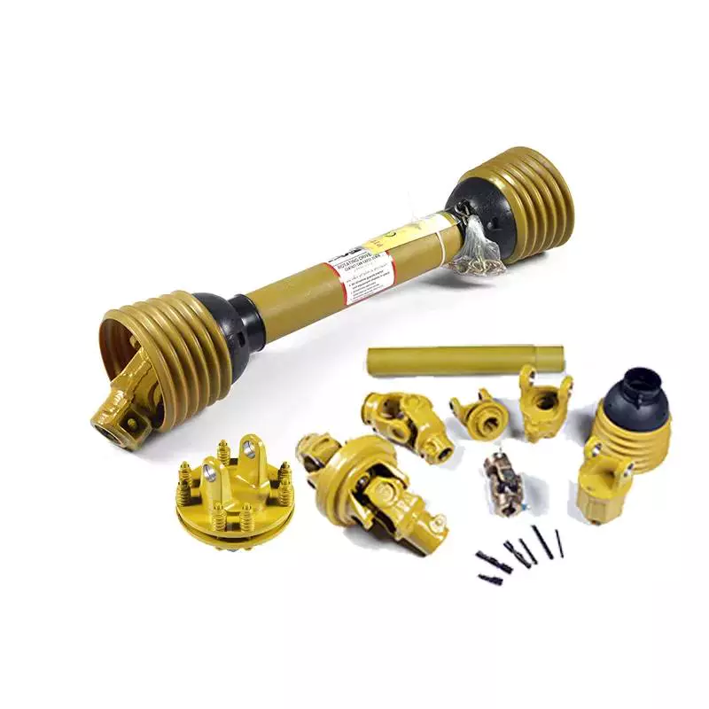
Independent PTO
Independent PTO shafts can be mechanical or hydraulic. The mechanical type has a separate on/off selector and control lever, whereas hydraulic PTOs have just one. The mechanical version is preferred for tractors that need to operate at lower speeds and for applications such as baling and tilling. The hydraulic version reduces noise and vibration.
Another advantage of an independent PTO is that it is easy to engage. Instead of engaging a clutch, you simply shift the PTO selector lever away from ‘OFF’ and flip the PTO switch to “ON.” This lever is usually located on the right hand side of the operator’s seat.
The ISO 500 standard provides specifications for independent PTO shafts. This specification lays out the size of the shaft, number of splines and the location of the PTO. In addition, it specifies the maximum RPM and shaft diameter for a PTO. The original ISO 500-3 specification calls for 540 revolutions per minute for shafts with six splines.
Another benefit of an independent PTO is its ability to be engaged or disengaged without using the transmission clutch. The lever can be pressed halfway or fully to engage an independent PTO. The independent PTO also allows you to stop the tractor while it is in motion. Independent PTOs are available in hydrostatic or mechanical configurations, and are particularly popular with hydrostatic drives.
LPTO shaft guard
An LPTO shaft guard prevents accidental rotational collisions by covering the shaft of a PTO. A PTO shaft is a moving part that can entrap a person’s legs, arms, and clothing. In a pinch, a person could become entangled in the shaft and suffer a serious injury. A PTO shaft guard is a great way to protect yourself against these dangerous incidents.
PTO mishaps can cause severe injuries and even fatalities. To prevent this, equipment manufacturers have made strides in improving the design and construction of their PTO drive shafts. A PTO shaft guard will protect the drive shaft from entanglement and tearing. Proper installation and maintenance of a PTO shaft guard can help protect the tractor, PTO, and other machinery.
Tractor PTO shaft guards are made from durable plastics and can be installed easily. They keep all the parts of the tractor in place and prevent accidents during operation. These parts are vital components for many farm equipments. A 540 RPM shaft can pull a person from a distance of five feet. A PTO shaft guard will prevent this from happening by keeping clothing from becoming entangled in the shaft.
Another important component of a PTO system is the master shield, which covers the PTO stub and the input driveline shaft of an implement. The master shield protects both the tractor PTO stub and the connection end of the input driveline shaft. It extends over the PTO stub on three sides. Many people never replace their master shields because they are too expensive.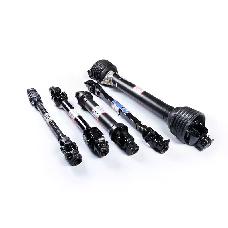
Safety of handling a pto shaft
Handling a PTO shaft safely is a vital component of tractor safety. Safety shields must be properly fastened to the shaft to prevent any accidents. The shield should also be inspected and maintained regularly. Otherwise, foreign materials, including clothing, can enter the shaft’s bearings. It is also important to walk around the rotating shaft whenever possible.
Power takeoff shafts are used to transfer mechanical power from farm tractors to implements. However, improper handling of these devices can lead to severe injuries, including amputation and multiple fractures. Spinal injuries are also common, especially if an individual is rotated around the shaft.
Operator awareness is key to avoiding PTO entanglement. Performing repairs while a machine is in operation or wearing loose, frayed clothing may lead to injury. It is also important to read the manufacturer’s instructions before operating a PTO. Lastly, it is important to never operate a PTO while the engine is running.
PTO shafts should be protected by ‘U’ or ‘O’ guards on the tractor and the attached implement. It is also important to use a PTO stand. As with any mechanical part, handling a PTO shaft requires care. Always ensure that the tractor is off before working and remove the key before working on it. Also, it is important to avoid stepping on the drive line or going under it. Make sure you wear protective clothing and shoes. Avoid wearing clothes that have laces as they could become entangled in the shaft and cause injury.
The connection to the PTO shaft should be close to the ground. If it is not, kneel on a flat surface. A piece of carpet, automobile floor-mat or cardboard can work well. Then, align the splines on the PTO shaft. To do this, press the locking pin button, then pull the ball-lock collar back, and then push the shaft onto the PTO.

editor by CX 2023-05-16
China Top Grade Tractor Clutch For Sale Pto Drive Shaft With Clutch (Ce Certificate) with high quality
Error:获取返回内容失败,
Your session has expired. Please reauthenticate.
drive shaft carrier bearing
editor by czh 2023-03-05
China Best Sales Agricultural Sickle Forage Harvester For Sale Tractor Rear Mounted Three-point Suspension Reciprocating Reinforced Square Mower agricultural pto gearbox
Situation: New
Application: Forage Grass
Functioning Width(mm): 1800 mm
Tractor Electricity(HP): twelve – fifty HP
Equipment Sort: Forage Machinery
Type: Sickle Bar Mower
Drive Variety: PTO Shaft Drive, PTO Push
Usage: Straw Mower
Fat: 180Kg
Certificate: Ce
Important Offering Factors: Substantial Productiveness
Warranty: 1 Year
Marketing Type: Sizzling Merchandise 2571
Video outgoing-inspection: Presented
Equipment Check Report: Presented
Guarantee of core components: 1 12 months
Core Components: Gearbox, Knife
Showroom Place: None
Relevant Industries: Farms, Property Use, Yard
Merchandise name: Reciprocating Square Mower
Cutting width (mm): 1800Mm
Design: 9GB-1.8
Colour: Consumer Need
Crucial phrases: Sickle Bar Mower
Stubble Height: 50-80Mm
Linkage: A few Stage Mounted
Operating pace: 540 R/Min
Soon after-income Support Presented: Video clip technological support, On the internet assistance
Right after Guarantee Provider: Spare parts
Regional Service Location: None
Packaging Information: Iron Body Deal/Wooden Box Bundle
Port: Every single Port In China
Agricultural Sickle Forage Harvester For Sale /Tractor Rear Mounted Three-position Suspension Reciprocating Bolstered Sq. Mower
The 9GB collection lawn mower produced and produced by Xihu (West Lake) Dis.g equipment is a rear mounted semi suspended (suspended) reciprocating lawn mower, which can be equipped with twelve-50 horsepower tractors. The utility model utilizes the offset crank connecting rod mechanism to drive the cutter to lower grass, which is suitable for flat grassland in agriculture, SWL worm bolt lifter jack screw gearbox harmonic push reducer cycloidal equipment box .5hp motor gearbox lg washing machine gearbo forestry and pastoral places, sloping land, hills and other different circumstances. It is employed for harvesting all-natural forage and planting forage, alfalfa, reed, green fodder, and so forth., and can also create massive garden such as manor, NMRV030 nmrv050 worm gearbox small reducer nmrv box equipment worm aluminum housing light weight reducer golfing training course, and so forth.
Excellent Features
The tractor’s electrical power output shaft drives the slicing motion of the cutter, the 3-position linkage controls the increase and slide of the apply, and controls the tractor’s electrical power output system to recognize the motion or end of the cutter. The cutter is operated by a single tractor driver with good mobility. The equipment has the characteristics of compact composition, convenient operation, powerful cutting, Agricultural machinery bearing deep groove ball bearing LM60P3049 ball bearing alternative for John Deere, CLAAS, CNH reduced stubble and neat chopping.
Solution Parameters
| Identify | Reciprocating Mower / Sickle Bar Mower | |||
| Design | 9GB-1.four | 9GB-1.six | 9GB-1.eight | 9GB-2.1 |
| Chopping Width | 1400Mm | 1600Mm | 1800Mm | 2100Mm |
| Slicing Peak | 50-80Mm | |||
| Doing work Pace | 4-10Km/h | |||
| PTO Pace | 540R/min | |||
| Matched Power | 12-40Hp | |||
| Cutter Stroke | 76 | |||
| Linkage | Three Level Mounted | |||
| Excess weight | 160Kg | 180Kg | 190Kg | 210Kg |
Depth Drawing
Relevant Forage Machinery
Manufacturing unit Corner
Company Information
Solution Certification
FAQ
Calculating the Deflection of a Worm Shaft
In this article, we’ll discuss how to calculate the deflection of a worm gear’s worm shaft. We’ll also discuss the characteristics of a worm gear, including its tooth forces. And we’ll cover the important characteristics of a worm gear. Read on to learn more! Here are some things to consider before purchasing a worm gear. We hope you enjoy learning! After reading this article, you’ll be well-equipped to choose a worm gear to match your needs.
Calculation of worm shaft deflection
The main goal of the calculations is to determine the deflection of a worm. Worms are used to turn gears and mechanical devices. This type of transmission uses a worm. The worm diameter and the number of teeth are inputted into the calculation gradually. Then, a table with proper solutions is shown on the screen. After completing the table, you can then move on to the main calculation. You can change the strength parameters as well.
The maximum worm shaft deflection is calculated using the finite element method (FEM). The model has many parameters, including the size of the elements and boundary conditions. The results from these simulations are compared to the corresponding analytical values to calculate the maximum deflection. The result is a table that displays the maximum worm shaft deflection. The tables can be downloaded below. You can also find more information about the different deflection formulas and their applications.
The calculation method used by DIN EN 10084 is based on the hardened cemented worm of 16MnCr5. Then, you can use DIN EN 10084 (CuSn12Ni2-C-GZ) and DIN EN 1982 (CuAl10Fe5Ne5-C-GZ). Then, you can enter the worm face width, either manually or using the auto-suggest option.
Common methods for the calculation of worm shaft deflection provide a good approximation of deflection but do not account for geometric modifications on the worm. While Norgauer’s 2021 approach addresses these issues, it fails to account for the helical winding of the worm teeth and overestimates the stiffening effect of gearing. More sophisticated approaches are required for the efficient design of thin worm shafts.
Worm gears have a low noise and vibration compared to other types of mechanical devices. However, worm gears are often limited by the amount of wear that occurs on the softer worm wheel. Worm shaft deflection is a significant influencing factor for noise and wear. The calculation method for worm gear deflection is available in ISO/TR 14521, DIN 3996, and AGMA 6022.
The worm gear can be designed with a precise transmission ratio. The calculation involves dividing the transmission ratio between more stages in a gearbox. Power transmission input parameters affect the gearing properties, as well as the material of the worm/gear. To achieve a better efficiency, the worm/gear material should match the conditions that are to be experienced. The worm gear can be a self-locking transmission.
The worm gearbox contains several machine elements. The main contributors to the total power loss are the axial loads and bearing losses on the worm shaft. Hence, different bearing configurations are studied. One type includes locating/non-locating bearing arrangements. The other is tapered roller bearings. The worm gear drives are considered when locating versus non-locating bearings. The analysis of worm gear drives is also an investigation of the X-arrangement and four-point contact bearings.
Influence of tooth forces on bending stiffness of a worm gear
The bending stiffness of a worm gear is dependent on tooth forces. Tooth forces increase as the power density increases, but this also leads to increased worm shaft deflection. The resulting deflection can affect efficiency, wear load capacity, and NVH behavior. Continuous improvements in bronze materials, lubricants, and manufacturing quality have enabled worm gear manufacturers to produce increasingly high power densities.
Standardized calculation methods take into account the supporting effect of the toothing on the worm shaft. However, overhung worm gears are not included in the calculation. In addition, the toothing area is not taken into account unless the shaft is designed next to the worm gear. Similarly, the root diameter is treated as the equivalent bending diameter, but this ignores the supporting effect of the worm toothing.
A generalized formula is provided to estimate the STE contribution to vibratory excitation. The results are applicable to any gear with a meshing pattern. It is recommended that engineers test different meshing methods to obtain more accurate results. One way to test tooth-meshing surfaces is to use a finite element stress and mesh subprogram. This software will measure tooth-bending stresses under dynamic loads.
The effect of tooth-brushing and lubricant on bending stiffness can be achieved by increasing the pressure angle of the worm pair. This can reduce tooth bending stresses in the worm gear. A further method is to add a load-loaded tooth-contact analysis (CCTA). This is also used to analyze mismatched ZC1 worm drive. The results obtained with the technique have been widely applied to various types of gearing.
In this study, we found that the ring gear’s bending stiffness is highly influenced by the teeth. The chamfered root of the ring gear is larger than the slot width. Thus, the ring gear’s bending stiffness varies with its tooth width, which increases with the ring wall thickness. Furthermore, a variation in the ring wall thickness of the worm gear causes a greater deviation from the design specification.
To understand the impact of the teeth on the bending stiffness of a worm gear, it is important to know the root shape. Involute teeth are susceptible to bending stress and can break under extreme conditions. A tooth-breakage analysis can control this by determining the root shape and the bending stiffness. The optimization of the root shape directly on the final gear minimizes the bending stress in the involute teeth.
The influence of tooth forces on the bending stiffness of a worm gear was investigated using the CZPT Spiral Bevel Gear Test Facility. In this study, multiple teeth of a spiral bevel pinion were instrumented with strain gages and tested at speeds ranging from static to 14400 RPM. The tests were performed with power levels as high as 540 kW. The results obtained were compared with the analysis of a three-dimensional finite element model.
Characteristics of worm gears
Worm gears are unique types of gears. They feature a variety of characteristics and applications. This article will examine the characteristics and benefits of worm gears. Then, we’ll examine the common applications of worm gears. Let’s take a look! Before we dive in to worm gears, let’s review their capabilities. Hopefully, you’ll see how versatile these gears are.
A worm gear can achieve massive reduction ratios with little effort. By adding circumference to the wheel, the worm can greatly increase its torque and decrease its speed. Conventional gearsets require multiple reductions to achieve the same reduction ratio. Worm gears have fewer moving parts, so there are fewer places for failure. However, they can’t reverse the direction of power. This is because the friction between the worm and wheel makes it impossible to move the worm backwards.
Worm gears are widely used in elevators, hoists, and lifts. They are particularly useful in applications where stopping speed is critical. They can be incorporated with smaller brakes to ensure safety, but shouldn’t be relied upon as a primary braking system. Generally, they are self-locking, so they are a good choice for many applications. They also have many benefits, including increased efficiency and safety.
Worm gears are designed to achieve a specific reduction ratio. They are typically arranged between the input and output shafts of a motor and a load. The two shafts are often positioned at an angle that ensures proper alignment. Worm gear gears have a center spacing of a frame size. The center spacing of the gear and worm shaft determines the axial pitch. For instance, if the gearsets are set at a radial distance, a smaller outer diameter is necessary.
Worm gears’ sliding contact reduces efficiency. But it also ensures quiet operation. The sliding action limits the efficiency of worm gears to 30% to 50%. A few techniques are introduced herein to minimize friction and to produce good entrance and exit gaps. You’ll soon see why they’re such a versatile choice for your needs! So, if you’re considering purchasing a worm gear, make sure you read this article to learn more about its characteristics!
An embodiment of a worm gear is described in FIGS. 19 and 20. An alternate embodiment of the system uses a single motor and a single worm 153. The worm 153 turns a gear which drives an arm 152. The arm 152, in turn, moves the lens/mirr assembly 10 by varying the elevation angle. The motor control unit 114 then tracks the elevation angle of the lens/mirr assembly 10 in relation to the reference position.
The worm wheel and worm are both made of metal. However, the brass worm and wheel are made of brass, which is a yellow metal. Their lubricant selections are more flexible, but they’re limited by additive restrictions due to their yellow metal. Plastic on metal worm gears are generally found in light load applications. The lubricant used depends on the type of plastic, as many types of plastics react to hydrocarbons found in regular lubricant. For this reason, you need a non-reactive lubricant.
