Product Description
| Product: | PTO Drive Shaft |
| Hardness: | 58-64HRC |
| Delivery Date: | 7-60 Days |
| MOQ: | 100 sets or according to stocks without minimum Qty. |
| Sample: | Aviliable |
| We could produce all kinds of PTO Drive Shaft and Parts according to customers’ requirement. | |
Packaging & Shipping
Packing:
Normal packing or According to your requirement.
Safe, complete and fast delivery of goods to customers.
Shipping: By sea
Payment Terms: T/T
Company Profile
| Business type | Manufacture |
| Location | Shiliwang Industrial Zone of HangZhou, ZheJiang ,China |
| Year Established | 2003 |
| Occupied area | 50 Acres |
| Company certification | CE, ISO9001,SGS |
| Main product | disc harrow, disc plough, trailer, boom sprayer , rotary tillers, potato planter ,plowing blade, plough blade, soil-loosening shovel and so on. With good quality, excellent performance, our products annually export to countries around the world, and we have gained the majority of customers trust. |
After Sales Service
After Service: 12 months guarantee of the main parts, we will send the guarantee parts together with the machine in your next order or we can send them by air express if you need it urgently.
FAQ
1.Q: Full price list for these products
A: If you need the price list for these products, please notify the product model so that I can quote you accordingly. Please understand we have a very wide product range, we don’t usually offer full products price list.
2. Q: Business terms
A: Shipment time: 25-40days after your payment
Shipment: By sea
Loading port: HangZhou port, China
Destination port: …To be advised
Payment: T/T
Warranty: 1 year
3.Q:How can I order from you?
A: Please send us your enquiry list; we will reply you within 2 working days.
4.Q:If the finger I look for are not in your catalogue, what should I do?
A: We can develop it according to your drawing or sample.
5. Q: Why choose CHINAMFG for cooperation?
A: Comparing with our competitors, we have much more advantages as follows:
– More than 30years in manufacturing farming machine
– More Professional Sales staffs to guarantee the better service
– More agri machines for your choice
– More New products into your range to avoid price competition
– Larger quantity production and shipment
– Better quality to guarantee better Credit.
– Faster delivery time: Only7days
– More stick quality checking before shipment.
– More reasonable after-sales service terms.
– More famous brand: Hongri” brand and “CE”ceitification.
– Lower repair rate and bad review rate
– We have American Branch to show our main products. We can give customers best service.
Please feel free to contact me if you have any questions.
Thanks. Have a nice day!
/* March 10, 2571 17:59:20 */!function(){function s(e,r){var a,o={};try{e&&e.split(“,”).forEach(function(e,t){e&&(a=e.match(/(.*?):(.*)$/))&&1
| Type: | Agricultural Spare Part |
|---|---|
| Usage: | Agricultural Spare Part-Pto |
| Material: | 20crmnti |
| Power Source: | Tractor |
| Weight: | 4lbs |
| After-sales Service: | 1year |
| Samples: |
US$ 1/Piece
1 Piece(Min.Order) | |
|---|
| Customization: |
Available
| Customized Request |
|---|

How do manufacturers ensure the compatibility of PTO shafts with different equipment?
Manufacturers employ various measures to ensure the compatibility of PTO (Power Take-Off) shafts with different equipment. Compatibility is crucial to ensure that PTO shafts can effectively transfer power from the power source to the driven machinery without compromising performance, safety, or ease of use. Here’s a detailed explanation of how manufacturers ensure compatibility:
1. Standardization: PTO shafts are designed and manufactured based on standardized specifications. These specifications outline the essential parameters such as shaft dimensions, spline sizes, torque ratings, and safety requirements. By adhering to standardized designs, manufacturers ensure that PTO shafts are compatible with a wide range of equipment that meets the same standards. Standardization allows for interchangeability, meaning that PTO shafts from one manufacturer can be used with equipment from another manufacturer as long as they conform to the same specifications.
2. Collaboration with Equipment Manufacturers: PTO shaft manufacturers often collaborate closely with equipment manufacturers to ensure compatibility. They work together to understand the specific requirements of the equipment and design PTO shafts that seamlessly integrate with the machinery. This collaboration may involve sharing technical specifications, conducting joint testing, and exchanging feedback. By working in partnership, manufacturers can address any compatibility issues early in the design and development process, resulting in PTO shafts that are tailored to the equipment’s needs.
3. Customization Options: PTO shaft manufacturers offer customization options to accommodate different equipment configurations. They provide flexibility in terms of shaft length, spline sizes, yoke designs, and coupling mechanisms. Equipment manufacturers can specify the required parameters, and the PTO shafts can be customized accordingly. This ensures that the PTO shafts precisely match the equipment’s power input/output requirements and connection methods, guaranteeing compatibility and efficient power transfer.
4. Testing and Validation: Manufacturers conduct rigorous testing and validation processes to ensure the compatibility and performance of PTO shafts. They subject the shafts to various tests, including torque testing, rotational speed testing, and durability testing. These tests verify that the PTO shafts can handle the expected power loads and operating conditions without failure. By validating the performance of the PTO shafts, manufacturers can ensure that they are compatible with a wide range of equipment and can reliably transfer power under different operating scenarios.
5. Compliance with Industry Standards: PTO shaft manufacturers adhere to industry standards and regulations to ensure compatibility. Organizations such as the American Society of Agricultural and Biological Engineers (ASABE) establish safety and performance standards for PTO shafts. Manufacturers design and produce their shafts in accordance with these standards, ensuring that their products meet the necessary requirements for compatibility and safety. Compliance with industry standards provides assurance to equipment manufacturers and end-users that the PTO shafts are compatible and suitable for use with different equipment.
6. Documentation and Guidelines: Manufacturers provide comprehensive documentation and guidelines to assist equipment manufacturers and end-users in ensuring compatibility. This documentation includes technical specifications, installation instructions, maintenance guidelines, and safety recommendations. The documentation helps equipment manufacturers select the appropriate PTO shaft for their equipment and provides guidance on proper installation and use. By following the manufacturer’s guidelines, equipment manufacturers can ensure compatibility and optimize the performance of the PTO shafts.
7. Ongoing Research and Development: PTO shaft manufacturers continuously invest in research and development to enhance compatibility with different equipment. They stay updated with industry trends, technological advancements, and evolving equipment requirements. This ongoing research and development enable manufacturers to improve the design, materials, and features of PTO shafts, ensuring compatibility with the latest equipment innovations and addressing any compatibility challenges that may arise.
By employing standardization, collaborating with equipment manufacturers, offering customization options, conducting thorough testing, complying with industry standards, providing documentation and guidelines, and investing in research and development, manufacturers ensure the compatibility of PTO shafts with different equipment. This compatibility allows for seamless integration, efficient power transfer, and optimal performance across a wide range of machinery and equipment in various industries.

How do PTO shafts handle variations in load and torque during operation?
PTO (Power Take-Off) shafts are designed to handle variations in load and torque during operation by employing specific mechanisms and features that ensure efficient power transfer and protection against overload conditions. Here’s a detailed explanation of how PTO shafts handle variations in load and torque:
1. Mechanical Design: PTO shafts are engineered with robust mechanical design principles that enable them to handle variations in load and torque. They are typically constructed using high-strength materials such as steel, which provides durability and resistance to bending or twisting forces. The shaft’s diameter, wall thickness, and overall dimensions are carefully calculated to withstand the expected torque levels and load variations. The mechanical design of the PTO shaft ensures that it can transmit power reliably and accommodate the dynamic forces encountered during operation.
2. Universal Joints: Universal joints are a key component of PTO shafts that allow for flexibility and compensation of misalignment between the power source and driven machinery. These joints can accommodate variations in angular alignment, which may occur due to changes in load or movement of the machinery. Universal joints consist of a cross-shaped yoke with needle bearings that allow for smooth rotation and transfer of torque, even when the shafts are not perfectly aligned. The design of universal joints enables PTO shafts to handle variations in load and torque while maintaining consistent power transmission.
3. Slip Clutches: Slip clutches are often incorporated into PTO shafts to provide overload protection. These clutches allow the PTO shaft to slip or disengage momentarily when excessive torque or resistance is encountered. Slip clutches typically consist of friction plates that can be adjusted to a specific torque setting. When the torque surpasses the predetermined limit, the clutch slips, preventing damage to the PTO shaft and connected equipment. Slip clutches are particularly useful when sudden changes in load or torque occur, providing a safety mechanism to protect the PTO shaft and associated machinery.
4. Torque Limiters: Torque limiters are another protective feature found in some PTO shafts. These devices are designed to automatically disengage the power transmission when a predetermined torque threshold is exceeded. Torque limiters can be mechanical, such as shear pin couplings or friction clutches, or electronic, utilizing sensors and control systems. When the torque exceeds the set limit, the torque limiter disengages, preventing further power transfer and protecting the PTO shaft from overload conditions. Torque limiters are effective in handling sudden spikes in torque and safeguarding the PTO shaft and associated equipment.
5. Maintenance and Inspection: Regular maintenance and inspection of PTO shafts are essential to ensure their proper functioning and ability to handle variations in load and torque. Routine maintenance includes lubrication of universal joints, inspection of shaft integrity, and tightening of fasteners. Regular inspections allow for early detection of wear, misalignment, or other issues that may affect the PTO shaft’s performance. By addressing maintenance and inspection requirements, operators can identify and address any concerns that may arise due to variations in load and torque, ensuring the continued safe and efficient operation of the PTO shaft.
6. Operator Awareness and Control: Operators play a crucial role in managing variations in load and torque during PTO shaft operation. They should be aware of the machinery’s operational limits, including the recommended torque ratings and load capacities of the PTO shaft. Proper training and understanding of the equipment’s capabilities enable operators to make informed decisions and adjust the operation when encountering significant load or torque changes. Operators should also be vigilant in monitoring the equipment’s performance, watching for any signs of excessive vibration, noise, or other indications of potential issues related to load and torque variations.
By incorporating robust mechanical design, utilizing universal joints, slip clutches, torque limiters, and implementing proper maintenance practices, PTO shafts are equipped to handle variations in load and torque during operation. These features ensure reliable power transmission, protect against overload conditions, and contribute to the safe and efficient functioning of the PTO shaft and the machinery it drives.
What is a PTO shaft and how is it used in agricultural and industrial equipment?
A power take-off (PTO) shaft is a mechanical component used in agricultural and industrial equipment to transfer power from a power source, such as an engine or motor, to another machine or implement. It is a driveline shaft that transmits rotational power and torque, allowing the connected equipment to perform various tasks. PTO shafts are commonly used in agricultural machinery, such as tractors, as well as in industrial equipment, including generators, pumps, and construction machinery. Here’s a detailed explanation of what a PTO shaft is and how it is used:
Structure and Components: A typical PTO shaft consists of a hollow metal tube with universal joints at each end. The hollow tube allows the shaft to rotate freely, while the universal joints accommodate angular misalignments between the power source and the driven equipment. The universal joints consist of a cross-shaped yoke with needle bearings, providing flexibility and allowing the transmission of power at varying angles. Some PTO shafts may also include a telescopic section to adjust the length for different equipment setups or to accommodate varying distances between the power source and the driven machine.
Power Transfer: The primary function of a PTO shaft is to transfer power and torque from the power source to the driven equipment. The power source, typically an engine or motor, drives the PTO shaft through a mechanical connection, such as a gearbox or a clutch. As the power source rotates, it transmits rotational force to the PTO shaft. The PTO shaft, in turn, transfers this rotational power and torque to the driven equipment, enabling it to perform its intended function. The torque and rotational speed transmitted through the PTO shaft depend on the power source’s characteristics and the gear ratio or clutch engagement.
Agricultural Applications: In agriculture, PTO shafts are commonly used in tractors to power various implements and attachments. The PTO shaft is connected to the tractor’s power take-off, a rotating drive shaft located at the rear of the tractor. By engaging the PTO clutch, the tractor’s engine power is transferred through the PTO shaft to the attached implements. Agricultural machinery, such as mowers, balers, tillers, sprayers, and grain augers, often rely on PTO shafts to receive power for their operation. The PTO shaft allows the implements to be powered directly by the tractor’s engine, eliminating the need for separate power sources and increasing the versatility and efficiency of agricultural operations.
Industrial Applications: PTO shafts also find extensive use in various industrial applications. Industrial equipment, such as generators, pumps, compressors, and industrial mixers, often incorporate PTO shafts to receive power from engines or electric motors. The PTO shaft connects the power source to the driven equipment, allowing it to operate and perform its intended function. In construction machinery, PTO shafts can be found in equipment like concrete mixers, hydraulic hammers, and post hole diggers, enabling the transfer of power from the machinery’s engine to the specific attachment or tool being used.
Safety Considerations: It is important to note that PTO shafts can pose safety risks if not handled properly. The rotating shaft can cause serious injuries if operators come into contact with it while it is in operation. To ensure safety, PTO shafts are often equipped with shielding or guards that cover the rotating shaft and universal joints, preventing accidental contact. It is crucial to maintain and inspect these safety features regularly to ensure their effectiveness. Additionally, operators should receive proper training on PTO shaft operation, including safe attachment and detachment procedures, as well as the use of personal protective equipment when working near PTO-driven machinery.
In summary, a PTO shaft is a mechanical component used in agricultural and industrial equipment to transmit power and torque from a power source to a driven machine or implement. It enables the direct power transfer from engines or motors to various equipment, increasing efficiency and versatility in agricultural and industrial operations. While PTO shafts offer significant benefits, operators must be aware of the associated safety considerations and take appropriate precautions to prevent accidents and injuries.


editor by CX 2024-01-09
China high quality CE Certificate Agricultural Machinery Potato Harvester Spare Parts Cardan Pto Drive Shaft and Farm Tractor Pto Shaft
Product Description
CE Certificate Agricultural Machinery Potato Harvester Spare Parts Cardan Pto Drive Shaft and Farm Tractor Pto Shaft
Product Description
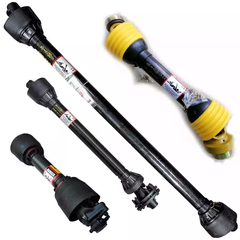
A Power Take-Off shaft (PTO shaft) is a mechanical device utilized to transmit power from a tractor or other power source to an attached implement, such as a mower, tiller, or baler. Typically situated at the rear of the tractor, the PTO shaft is driven by the tractor’s engine through the transmission.
The primary purpose of the PTO shaft is to supply a rotating power source to the implement, enabling it to carry out its intended function. To connect the implement to the PTO shaft, a universal joint is employed, allowing for movement between the tractor and the implement while maintaining a consistent power transfer.
Here is our advantages when compare to similar products from China:
1.Forged yokes make PTO shafts strong enough for usage and working;
2.Internal sizes standard to confirm installation smooth;
3.CE and ISO certificates to guarantee to quality of our goods;
4.Strong and professional package to confirm the good situation when you receive the goods.
Product Specifications
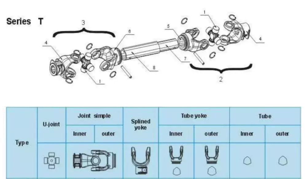
In farming, the most common way to transmit power from a tractor to an implement is by a driveline, connected to the PTO (Power Take Off) of the tractor to the IIC(Implement Input Connection). Drivelines are also commonly connected to shafts within the implement to transmit power to various mechanisms.
The following dimensions of the PTO types are available.
Type B:13/8″Z6(540 min)
Type D:13/8″Z21(1000 min)
Coupling a driveline to a PTO should be quick and simple because in normal use tractors must operate multiple implements. Consequently, yokes on the tractor-end of the driveline are fitted with a quick-disconnect system, such as push-pin or ball collar.
Specifications for a driveline, including the way it is coupled to a PTO, depend CZPT the implement.
Yokes on the llc side are rarely disconnected and may be fastened by quick-lock couplings (push-pin or ball collar).
Taper pins are the most stable connection for splined shafts and are commonly used in yokes and torque limiters. Taper pins are also often used to connect internal drive shafts on drivelines that are not frequently disconnected.
Torque limiter and clutches must always be installed on the implement side of the primary driveline.
Packaging & Shipping
Company Profile
HangZhou Hanon Technology Co.,ltd is a modern enterprise specilizing in the development,production,sales and services of Agricultural Parts like PTO shaft and Gearboxes and Hydraulic parts like Cylinder , Valve ,Gearpump and motor etc..
We adhere to the principle of ” High Quality, Customers’Satisfaction”, using advanced technology and equipments to ensure all the technical standards of transmission .We follow the principle of people first , trying our best to set up a pleasant surroundings and platform of performance for each employee. So everyone can be self-consciously active to join Hanon Machinery.
FAQ
1.WHAT’S THE PAYMENT TERM?
When we quote for you,we will confirm with you the way of transaction,FOB,CIFetc.<br> For mass production goods, you need to pay 30% deposit before producing and70% balance against copy of documents.The most common way is by T/T.
2.HOW TO DELIVER THE GOODS TO US?
Usually we will ship the goods to you by sea.
3.HOE LONG IS YOUR DELIVERY TIME AND SHIPMENT?
30-45days.
/* March 10, 2571 17:59:20 */!function(){function s(e,r){var a,o={};try{e&&e.split(“,”).forEach(function(e,t){e&&(a=e.match(/(.*?):(.*)$/))&&1
| Type: | Pto Shaft |
|---|---|
| Usage: | Agricultural Products Processing, Farmland Infrastructure, Tillage, Harvester, Planting and Fertilization, Grain Threshing, Cleaning and Drying, Agricultural Machinery,Farm Tractor |
| Material: | 45cr Steel |
| Samples: |
US$ 20/Piece
1 Piece(Min.Order) | Order Sample |
|---|
| Customization: |
Available
| Customized Request |
|---|
.shipping-cost-tm .tm-status-off{background: none;padding:0;color: #1470cc}
|
Shipping Cost:
Estimated freight per unit. |
about shipping cost and estimated delivery time. |
|---|
| Payment Method: |
|
|---|---|
|
Initial Payment Full Payment |
| Currency: | US$ |
|---|
| Return&refunds: | You can apply for a refund up to 30 days after receipt of the products. |
|---|

How do PTO drive shafts ensure efficient power transfer while maintaining safety?
PTO (Power Take-Off) drive shafts are designed to ensure efficient power transfer while prioritizing safety. These drive shafts incorporate various mechanisms and features to achieve both objectives. Here’s a detailed explanation of how PTO drive shafts ensure efficient power transfer while maintaining safety:
1. Robust Construction:
PTO drive shafts are typically constructed using high-quality materials such as steel or composite materials that offer strength and durability. The robust construction allows them to withstand the torque and power demands of the application, ensuring efficient power transfer without excessive flexing or deformation that could result in energy loss or premature failure.
2. Precise Alignment:
Efficient power transfer requires precise alignment between the PTO drive shaft, the primary power source (e.g., engine, transmission), and the implement or equipment being driven. Misalignment can lead to power loss, increased wear, and potential safety hazards. PTO drive shafts are designed with adjustable lengths or flexible couplings to accommodate variations in equipment size and ensure proper alignment, maximizing power transmission efficiency.
3. Connection Safety Features:
PTO drive shafts incorporate safety features to prevent accidents and minimize the risk of injury. One common safety feature is the use of shear pins or torque limiters. These components are designed to break or slip under excessive torque, protecting the drive shaft and connected equipment from damage. By sacrificing the shear pin, the PTO drive shaft disengages in case of overload, ensuring the safety of operators and preventing costly repairs.
4. Overload Protection:
Overload protection mechanisms are crucial for maintaining safety and preventing damage to the PTO drive shaft and associated equipment. Clutch systems or slip clutches can be employed to disengage the drive shaft when excessive torque or speed is encountered. These mechanisms allow the drive shaft to slip or disengage momentarily, preventing damage and reducing the risk of injury to operators or bystanders.
5. Shielding and Guarding:
PTO drive shafts are often equipped with shielding and guarding to prevent contact with moving parts. These protective covers ensure that operators and bystanders are shielded from rotating shafts, universal joints, and other potentially hazardous components. Proper shielding and guarding reduce the risk of entanglement, entrapment, or accidental contact, enhancing overall safety.
6. Compliance with Safety Standards:
PTO drive shafts are designed and manufactured to comply with relevant safety standards and regulations. These standards, such as ISO 500-1, specify requirements for power transmission components, including PTO drive shafts. Compliance with these standards ensures that the drive shafts meet necessary safety criteria and undergo rigorous testing to ensure their reliability and performance.
7. Regular Maintenance and Inspection:
Maintaining the safety and efficiency of PTO drive shafts requires regular maintenance and inspection. Operators should follow recommended maintenance schedules, including lubrication, inspection of components, and replacement of worn or damaged parts. Regular inspections help identify potential safety issues, such as worn bearings, damaged shielding, or compromised safety features, allowing for timely repairs or replacements.
8. Operator Training and Awareness:
Efficient power transfer and safety also depend on operator training and awareness. Operators should receive proper training on the safe operation and maintenance of PTO drive shafts. This includes understanding safety procedures, recognizing potential hazards, and being aware of the risks associated with improper use or maintenance. Promoting a culture of safety and providing ongoing training helps ensure that PTO drive shafts are used correctly and that potential risks are minimized.
By incorporating robust construction, precise alignment, connection safety features, overload protection, shielding and guarding, compliance with safety standards, regular maintenance and inspection, and operator training and awareness, PTO drive shafts can achieve efficient power transfer while maintaining a high level of safety. These measures help prevent accidents, protect equipment and operators, and ensure reliable and effective power transmission in various applications.

Can you provide real-world examples of machinery that use PTO drive shaft technology?
PTO (Power Take-Off) drive shaft technology is widely utilized in various machinery across different industries. It enables the transfer of power from a power source, such as an engine or motor, to driven equipment or implements. Here are some real-world examples of machinery that commonly use PTO drive shaft technology:
1. Agricultural Machinery:
PTO drive shafts are extensively used in agricultural machinery. Tractors, for instance, often feature a PTO that allows power to be transferred to a range of implements, including plows, cultivators, mowers, balers, and grain augers. These implements are connected to the PTO drive shaft, which provides the necessary power for their operation. PTO drive shafts play a key role in enhancing the efficiency and versatility of agricultural equipment.
2. Forestry Equipment:
In the forestry industry, PTO drive shafts are employed in various machinery used for wood processing and harvesting. Equipment such as wood chippers, stump grinders, log splitters, and portable sawmills often utilize PTO drive shafts to transmit power from tractors or other power sources. PTO drive shafts enable efficient and reliable operation of these forestry machines, contributing to productivity and effectiveness in the field.
3. Construction Machinery:
PTO drive shafts are also found in construction machinery, particularly in equipment that requires power for auxiliary functions. Examples include concrete mixers, concrete pumps, asphalt spreaders, and hydraulic attachments like augers and rotary brooms. PTO drive shafts enable the transfer of power from the main engine or hydraulic system to these auxiliary components, allowing for efficient operation and increased functionality on construction sites.
4. Industrial Equipment:
In the industrial sector, PTO drive shafts are utilized in various types of equipment. For example, industrial mixers, centrifugal pumps, air compressors, and generators often incorporate PTO drive shafts to obtain power from a prime mover or power source. This power transfer mechanism allows these machines to operate effectively and perform their intended functions in industries such as manufacturing, processing, and energy production.
5. Landscaping and Groundskeeping Equipment:
PTO drive shafts are commonly used in landscaping and groundskeeping equipment. Implements like rotary mowers, flail mowers, leaf blowers, and spreaders often rely on PTO drive shafts to receive power from tractors or other utility vehicles. PTO drive shafts enable efficient and precise cutting, mowing, and debris removal, contributing to the maintenance of parks, golf courses, sports fields, and other outdoor spaces.
6. Material Handling Machinery:
Machinery involved in material handling operations, such as forklifts, pallet jacks, and conveyor systems, may incorporate PTO drive shaft technology. PTO drive shafts provide power for auxiliary functions, such as lifting and moving loads, operating conveyor belts, or powering attachments like clamps or forks. This allows for efficient and controlled material handling in warehouses, distribution centers, and other industrial settings.
7. Marine and Boating Equipment:
PTO drive shafts are utilized in certain marine and boating applications. In larger vessels like commercial fishing boats or workboats, PTO drive shafts can transmit power from the main engine to auxiliary equipment such as winches, pumps, or generators. This helps facilitate various operations at sea, such as fishing, lifting heavy loads, or generating electricity for onboard systems.
These examples demonstrate the diverse range of machinery that incorporates PTO drive shaft technology. From agricultural and forestry equipment to construction, industrial, landscaping, material handling, and marine machinery, PTO drive shafts provide a reliable and efficient power transmission solution. Their widespread use across industries highlights the importance of PTO drive shafts in enhancing the functionality and performance of various types of equipment.

Can you explain the components and function of a PTO drive shaft system?
A PTO (Power Take-Off) drive shaft system consists of several components that work together to transfer power from a primary power source, such as a tractor or engine, to various implements or machinery. Each component plays a specific role in ensuring the efficient and reliable transmission of rotational power. Here’s a detailed explanation of the components and their functions within a PTO drive shaft system:
1. Primary Power Source:
The primary power source is typically a tractor or engine equipped with a PTO output shaft. This shaft generates rotational power from the engine’s crankshaft or transmission, acting as the starting point for power transmission.
2. PTO Output Shaft:
The PTO output shaft is a rotating shaft located on the primary power source, specifically designed to transfer power to external devices. It is typically located at the rear of a tractor and may have various spline configurations to accommodate different types of PTO drive shafts.
3. PTO Drive Shaft:
The PTO drive shaft is the main component of the system, responsible for transmitting power from the primary power source to the implement or machinery. It consists of a rotating shaft with splines at both ends. One end connects to the PTO output shaft, while the other end connects to the input shaft of the implement. The drive shaft rotates at the same speed as the primary power source, effectively delivering power to the implement.
4. Splined Connections:
The splined connections on the PTO drive shaft and the PTO output shaft of the primary power source provide a secure and robust connection. These splines ensure proper alignment and torque transmission between the two shafts, enabling efficient power transfer while accommodating varying distances and alignments.
5. Safety Guards and Shields:
PTO drive shaft systems often incorporate safety guards and shields to protect operators from potential hazards associated with rotating components. These guards and shields cover the rotating parts of the drive shaft, reducing the risk of entanglement or contact during operation.
6. Telescoping or Sliding Mechanism:
Some PTO drive shafts feature a telescoping or sliding mechanism. This allows the drive shaft to be adjusted in length, accommodating different distances between the primary power source and the implement. The telescoping or sliding mechanism ensures proper alignment and prevents excessive tension or binding of the drive shaft.
7. Shear Pins or Clutch Mechanism:
To protect the PTO drive shaft and the machinery from excessive loads or sudden shocks, shear pins or a clutch mechanism may be incorporated. These safety features are designed to disconnect the drive shaft from the primary power source in the event of an overload or sudden impact, preventing damage to the drive shaft and associated equipment.
8. Maintenance and Lubrication Points:
PTO drive shaft systems require regular maintenance and lubrication to ensure optimal performance and longevity. Lubrication points are typically provided to allow for the application of grease or oil to reduce friction and wear. Regular inspections and maintenance help identify any issues or wear in the components, ensuring safe and efficient operation.
9. Implement Input Shaft:
The implement input shaft is the counterpart to the PTO drive shaft on the implement or machinery side. It connects to the PTO drive shaft and receives power for driving the specific machinery or performing various tasks. The input shaft is precisely aligned with the drive shaft to ensure efficient power transfer.
In summary, a PTO drive shaft system consists of components such as the primary power source, PTO output shaft, PTO drive shaft, splined connections, safety guards, telescoping or sliding mechanisms, shear pins or clutch mechanisms, maintenance and lubrication points, and the implement input shaft. Together, these components enable the efficient and reliable transfer of rotational power from the primary power source to the implement or machinery, allowing for a wide range of tasks and applications in agricultural and industrial settings.
editor by CX 2023-12-22
China high quality ND Brand Pto Drive Shaft Cardan Transmission Tractor Parts pto shaft adaptor
Product Description
Product Description
Company Profile
In 2571, HangZhou CZPT Machinery Co.,ltd was established by Ms. Iris and her 2 partners(Mr. Tian and Mr. Yang) in HangZhou city(ZHangZhoug province, China), all 3 Founders are engineers who have more than averaged 30 years of experience. Then because the requirements of business expansion, in 2014, it moved to the current Xihu (West Lake) Dis. Industrial Zone (HangZhou city, ZHangZhoug province, China).
Through our CZPT brand ND, CZPT Machinery delivers agricultural solutions to agriculture machinery manufacturer and distributors CZPT through a full line of spiral bevel gearboxes, straight bevel gearboxes, spur gearboxes, drive shafts, sheet metal, hydraulic cylinder, motors, tyre, worm gearboxes, worm operators etc. Products can be customized as request.
We, CZPT machinery established a complete quality management system and sales service network to provide clients with high-quality products and satisfactory service. Our products are sold in 40 provinces and municipalities in China and 36 countries and regions in the world, our main market is the European market.
Our factory
Certifications
Why choose us?
1) Customization: With a strong R&D team, and we can develop products as required. It only takes up to 7 days for us to design a set of drawings. The production time for new products is usually 50 days or less.
2) Quality: We have our own complete inspection and testing equipment, which can ensure the quality of the products.
3) Capacity: Our annual production capacity is over 500,000 sets, also, we also accept small quantity orders, to meet the needs of different customer’s purchase quantities.
4) Service: We focus on offering high-quality products. Our products are in line with international standards and are mainly exported to Europe, Australia, and other countries and regions.
5) Shipment: We are close to HangZhou and ZheJiang ports, to provide the fastest shipping service.
Packaging & Shipping
FAQ
Q: Are you a trading company or manufacturer?
A: We’re factory and providing gearbox ODM & OEM services for the European market for more than 10 years
Q: Do you provide samples? is it free or extra?
A: Yes, we could offer the sample for free charge but do not pay the cost of freight.
Q: How long is your delivery time? What is your terms of payment?
A: Generally it is 40-45 days. The time may vary depending on the product and the level of customization.
For standard products, the payment is: 30% T/T in advance,balance before shipment.
Q: What is the exact MOQ or price for your product?
A: As an OEM company, we can provide and adapt our products to a wide range of needs.
Thus, MOQ and price may greatly vary with size, material and further specifications; For instance, costly products or standard products will usually have a lower MOQ. Please contact us with all relevant details to get the most accurate quotation.
If you have another question, please feel free to contact us.
| Type: | Agricultural Pto/Drive Shaft |
|---|---|
| Usage: | Agricultural Products Processing, Farmland Infrastructure, Tillage, Harvester, Planting and Fertilization, Grain Threshing, Cleaning and Drying |
| Material: | Carbon Steel |
| Power Source: | Tractor or Motor |
| Weight: | 5lbs |
| After-sales Service: | 5 Years |
| Customization: |
Available
| Customized Request |
|---|
PTO Shaft Safety Chains
PTO shaft is the part of a tractor that helps transfer power from the tractor to the equipment it is hooked to. A PTO shaft is important if you have a tiller or bush hog. The correct PTO shaft size is crucial for both the tractor and the equipment. If the PTO shaft size is not correct for your equipment, it may not work.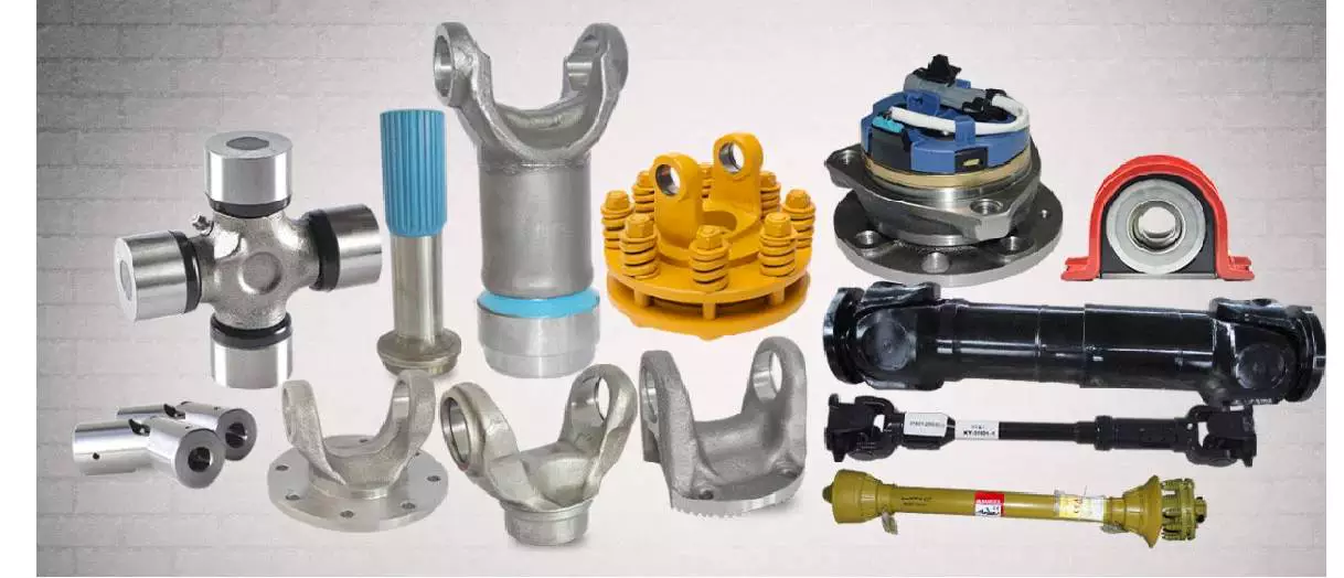
Safety chains
<br/Safety chains are an essential part of securing your PTO shaft. They prevent a rotating plastic shield from coming loose and causing injury or damage. It is important to protect your PTO and any other drive shafts on your machine. Watch the video below for more information about the dangers of unguarded PTOs.
PTOs are an efficient way to transfer mechanical power between tractors and implements. They helped revolutionize North American agriculture during the 1930s. Despite their convenience, PTOs have also proven to be one of the most common farm machinery hazards. This fact sheet outlines several important PTO safety precautions.
Safety chains for PTO shafts are necessary to protect both tractor and implement from damage. The PTO shaft must be attached properly to the tractor and the implement before starting the equipment. Before operating, be sure that the safety chains are positioned in a way that allows them to fully move. When operating the PTO, avoid being too aggressive as this can damage the drive line and shaft. For further safety, make sure to fit a torque limiter or clutch on the implement end of the PTO shaft.
PTOs are great for plowing, mowing, and shredding, but they also have potential to cause injuries if you don’t use a safety chain. It’s best to get a chain that is long enough to prevent injuries. Also, be sure that the PTO shaft does not compress completely at any point during the operating range. There should be several inches of overlap in the longest operating extension of the PTO.
Another common hazard with PTOs is IID shafts. While many machines and tractors have driveline guards, these are often missing. If you have a PTO with an IID, you should consider installing a safety chain.
Shield
A swingable tractor PTO shaft shield assembly consists of an inverted U-shaped shield member slidably attached to a bracket. It extends above the PTO shaft and has several notches and pins that engage each other. It can be held in a number of positions and can be retracted when not in use. It also includes a cover member that covers the space between the shield and tractor and abuts the raised portion of the shield member.
The PTO shaft shield is typically made of plastic, but it can also be made of metal. Plastic is less likely to break or damage than metal. The shield is supported by a bracket 51 with a curved distal end 57 and a non-metallic guard 59. When used in conjunction with a bracket, a PTO shaft shield should be properly installed to prevent damage to the shaft.
Keeping the PTO shaft shield in good condition is crucial to the safety of your tractor and your workers. An improperly installed PTO shaft shield can result in severe injuries. It may also ensnare or strike people in the vicinity. Proper maintenance will prevent many of these injuries. Equipment manufacturers have made great strides in reducing the risks of PTO mishaps. Operators are also responsible for keeping the shields in good condition. Removing the guards will only increase the risk to the operator.
A PTO shaft shield is a tubular assembly that is mounted on the tractor PTO shaft. It consists of two telescopic pieces that are held in place by shield support bearings. This shield protects the PTO shaft and the universal joints from debris and prevents premature wear. The shield can be easily removed and replaced if necessary.
IID shaft guard
The IID shaft guard is a safety device used to protect PTO powered machinery from the possibility of separating while in use. The shaft, which is a telescoping shaft, is attached to the PTO stub on tractors. The telescopic feature is convenient when moving across uneven ground. However, this type of shaft can cause serious injury if it separates while in use.
The IID shaft guard can prevent these injuries by completely covering the shaft. The guard is made of metal or plastic and rotates along with the shaft. A person can react in less than five tenths of a second, making the IID shaft guard an important part of PTO safety.
PTO shafts rotate at speeds as high as 540 rpm, which is very fast. A limb could be wrapped around the driveline shaft, causing a serious injury or death. Because of the speed of a PTO, it can be difficult for an individual to discern whether it is engaged or not and may not be aware of the danger.
An IID shaft guard should be fitted to every tractor PTO shaft. It should be tested and rotated regularly. It is also important to keep the tractor engine off when working around the PTO shaft. Using a drawbar to protect driveline components is also important. It will prevent stress on the driveline and reduce the possibility of separation.
Overrunning clutch
An overrunning clutch on a PTO shaft is a mechanism that allows the PTO shaft to rotate freely in one direction while restricting the speed of the implement being hauled behind the tractor. This clutch is also useful for preventing the speed of the implement from exceeding the speed of the tractor while slowing down. It comes in two basic configurations, one for a clockwise and the other for a counter-clockwise direction.
Another type of overrun clutch is used on tractors with a PTO driven bush hog. A bush hog has a flywheel and blades that drive the transmission through the PTO shaft. Without an overrunning clutch, these implements would freewheel while the tractor is driving and would potentially break the shaft.
A PTO overrunning clutch prevents power from backfeeding into the transmission, the part that transmits power to the rear wheels. Without an overrunning clutch, the tractor could backfeed power, causing an accident if the blade assembly hits an object. As such, it is essential to use the overrunning clutch to ensure that your tractor will be safe.
Direction of rotation
Despite its name, the direction of rotation of a PTO shaft can change if necessary. Most PTOs have a single-direction rotation, but you can often reverse the direction by installing a reverse PTO adapter. However, you should only use reverse PTOs when absolutely necessary.
A standard PTO rotation direction has been defined by the International Organization for Standardization (ISO). It is considered necessary to adhere to this standard, as improper rotation can cause damage to implements attached to a PTO. This standard helps farmers avoid problems such as ruined implements. While the direction of rotation of a PTO shaft is not always the same for all PTOs, there are some tractors that allow it to rotate both ways, while others have no restrictions.
The direction of rotation of a PTO shaft can be changed by using a hydraulic pump. Another way to connect a PTO is through a “sandwich” type split shaft unit. These units are mounted between the transmission and engine, and they usually receive drive directly from the engine shaft. They can also deliver complete engine power to a PTO. However, you must modify your vehicle’s driveline to install such a split-shaft unit.

editor by CX 2023-05-04
China Top Grade Tractor Clutch For Sale Pto Drive Shaft With Clutch (Ce Certificate) with high quality
Error:获取返回内容失败,
Your session has expired. Please reauthenticate.
drive shaft carrier bearing
editor by czh 2023-03-05
China Farm Agricultural Wheel Tractor 100HP with High Quality pto shaft danger
Product Description
Wholesale price tag 80,ninety,100HP 4x4WD farm tractors for agriculture
Product Screen
OPPTIONAL ATTACHMENTS
We have a lot more than 30 sorts of attachments, All varieties of attachments can be replaced, It can be tailored to your specifications.
Product Parameters
|
major technological parameters |
|||
|
Design |
LT1004-1, Wheel kind |
||
|
Driving sort |
Four wheel drive |
||
|
Power |
100HP |
||
|
Steering technique type |
Complete hydraulic steering |
||
|
Common pace of electrical power output shaft |
540/760r/min | ||
| Quantity of gears (ahead/backward) | 12/twelve | ||
| Motor | HangZhouhong | ||
| External dimension (L × W × H) | 4190×1790×2690mm | ||
| Variety of hydraulic output teams | 2 | ||
| Kind of suspension | Three-level rear suspension | ||
Software
Packaging & Shipping
LUGONG Firm
ZheJiang Lugong Machinery Co., Ltd. was founded in March 2000. Our business is the backbone enterprise of design equipment national wide. It covers a land of 200 thousand sq. meters and has 1100 employees, 88 of whom are engineers and professionals.
Our company mostly creates loaders, excavators, tippers, tricycles and so on. Products are largely sell to above 20 provinces in China and export to dozens of countries and areas in Africa, Southeast Asia, South America and Russia. The high quality and efficiency of our modest farm-use loaders and design tippers are in foremost placement of the market all through the nation and properly received by users. Now, “Lu Gong” manufacturer loaders and tippers have acquired acceptance by sellers and uses all over China.
We target on top quality, overall performance and consider of consumers as always. In administration, we’ve reached a new stage by adopting ISO 9001:2015 international good quality management method.
We would like to build in economic building by holding our old and new close friends and users’ hands by adhering to our organization philosophy of ” Driven by science and technological innovation, in search of survival by good quality, benefiting by handling and successful industry by provider” and spirit of ” Pioneering, innovating and pursuing excellence”.
FAQ
one.Are you a manufacture or trading firm?
We are a professional producer and we can provide tractors from 25Hp-100HP and implements.
2.what is actually your MOQ?
1 device.
three.How long is the direct time?
Normally 15-25 times. Depands on the quantity of your order.
4.what’s your payment phrases?
Usually we use T/T We also take other payment phrases, this sort of as Western Union, PayPal and L/C.
five.Can be used for which implements?
Loader, Backhoe, Harrow, Mower, Plough, Planter, Trailer, Slasher, Snow blower or as per your specifications.
|
US $9,100-9,485 / UNITS | |
1 UNITS (Min. Order) |
###
| Type: | Wheel Tractor |
|---|---|
| Usage: | Farm Tractor, Garden Tractor, Lawn Tractor |
| Certification: | ISO, CE |
| Drive Wheel: | 4WD |
| Emission Standard: | Euro II |
| Fuel: | Gas / Diesel |
###
| Samples: |
US$ 9485/Piece
1 Piece(Min.Order) |
|---|
###
| Customization: |
Available
|
|---|
###
|
main technical parameters |
|||
|
Model |
LT1004-1, Wheel type |
||
|
Driving type |
4WD |
||
|
Power |
100HP |
||
|
Steering system type |
Full hydraulic steering |
||
|
Standard speed of power output shaft |
540/760r/min | ||
| Number of gears (forward/backward) | 12/12 | ||
| Engine | Dongfanghong | ||
| External dimension (L × W × H) | 4190×1790×2690mm | ||
| Number of hydraulic output groups | 2 | ||
| Type of suspension | Three-point rear suspension | ||
|
US $9,100-9,485 / UNITS | |
1 UNITS (Min. Order) |
###
| Type: | Wheel Tractor |
|---|---|
| Usage: | Farm Tractor, Garden Tractor, Lawn Tractor |
| Certification: | ISO, CE |
| Drive Wheel: | 4WD |
| Emission Standard: | Euro II |
| Fuel: | Gas / Diesel |
###
| Samples: |
US$ 9485/Piece
1 Piece(Min.Order) |
|---|
###
| Customization: |
Available
|
|---|
###
|
main technical parameters |
|||
|
Model |
LT1004-1, Wheel type |
||
|
Driving type |
4WD |
||
|
Power |
100HP |
||
|
Steering system type |
Full hydraulic steering |
||
|
Standard speed of power output shaft |
540/760r/min | ||
| Number of gears (forward/backward) | 12/12 | ||
| Engine | Dongfanghong | ||
| External dimension (L × W × H) | 4190×1790×2690mm | ||
| Number of hydraulic output groups | 2 | ||
| Type of suspension | Three-point rear suspension | ||
Choosing the Right PTO Shaft
There are several different types of PTO shaft. These include the Transmission PTO, the Economy PTO, the Type 4″ pto shaft, and the Two-stage clutch pto shaft. It is important to choose the correct one to ensure a smooth operation. When choosing a PTO shaft, consider the characteristics and uses of each type.
Transmission PTO
 If you have been experiencing trouble with your Transmission PTO shaft, you may want to take it to a mechanic to have it looked at. A PTO problem can be frustrating and costly to fix. Here are some tips for resolving PTO problems. Start by checking your transmission oil and air pressure levels. Also, check for cracked or kinked hoses and screens. If none of these steps resolve the issue, you may need to replace your PTO.
There are two types of Transmission PTO shafts, Type 1 and Type 2. The first type was designed to be used for 540 rpm applications. Later versions were designed to handle higher PTO powers, and the diameter was changed to increase its speed. Both types have different diameters, so be sure to check the spline count.
Transmission PTOs are commonly used between tractors and farm equipment. These PTOs have the feature of a universal transmission, although the input and output ends are not always on the same plane. The drive shaft is also able to vary the angle between input and output ends. This allows the drive shaft to operate within a specified left and right expansion range.
When replacing a transmission PTO, make sure you check the shaft’s speed and backlash before installing it. In addition, check the transmission gears to ensure they are in good condition. Experts from suppliers recommend inspecting and replacing any debris on the gaskets. They also recommend setting backlash units between the transmission and PTO. In general, backlash units should range from 6,000 to 12,000 units.
To maintain the efficiency of your Transmission PTO, it is necessary to maintain the proper oil level. Make sure you regularly check the PTO fluid and filter. A change of fluid and filter is recommended every 75,000 miles and 300,000 miles. Using a dial indicator can help you to check backlash and prevent damage to the PTO or mating gear.
Economy PTO
 The Economy PTO shaft allows you to reduce the engine speed when driving your PTO. This mode uses different gears to adjust the PTO shaft revs. The cab-mounted control/monitoring unit 14 uses the PTO speed information to set the parameters of the PTO. In order to operate this system, you must be aware of the lever 21 position and the type of shaft fitted.
The ratio of the input shaft 7 and the output shaft 22 determines the precise value. The ratio also depends on the type of PTO shaft and the ratio of the gearbox. There are two different types of PTO shafts, and each has different toothed wheels. To choose the right one, you should know the ratio of the shaft and the gearbox.
A Domestic PTO shaft is the most common type used in North America. It comes in a wide range of diameters and splines and can be used on a variety of applications. It is durable and is resistant to pressure, impacts, and tension. It is also equipped with a shear pin and slip clutch to protect the PTO from common obstacles.
An Economy PTO shaft enables your tractor to run at lower rpms, reducing noise and vibrations. It is perfect for a variety of agricultural equipment and is controlled by your tractor’s transmission. It is available in two types: mechanical and hydraulic. A mechanical version has a clutch, while a hydraulic version has a lever to control the torque.
The Economy PTO shaft allows you to reduce fuel costs and increase productivity by up to 2%. It also reduces noise in the cab, which is a plus. Its auto-mode feature helps you operate the Economy PTO with ease. This system can also be programmed to automatically disengage the PTO when the linkage is raised.
Two-stage clutch on pto shaft
 If you’re looking to get the most out of your tractor, you should check the clutch for two-stage operation. Two-stage clutches use two separate stages to disengage the PTO and gears. If the clutch does not disengage when you push the pedal, you’ll need to adjust it. Rust buildup can cause the clutch to stick and require a rebuild or replacement. Fortunately, there are many ways to check whether your clutch is slipping.
A two-stage clutch is commonly used in transmissions with live PTOs. The first stage operates the driven portion of the transmission, while the second stage controls the PTO. This arrangement allows the PTO to work independently of the transmission, which is especially useful in tractors that use mower attachments.
This two-stage clutch is usually accompanied by a gearbox. The gears in the PTO shaft are set up to rotate at a rate of 540 revolutions per minute (rpm) when the engine is running. The second clutch is designed to operate at a higher speed and can be used with different power sources.
A two-stage clutch on the PTO shaft is a good option if you’re using a tractor that doesn’t have a slip clutch. It will limit the tractor’s torque, so you’ll save money on fuel while doing work. It also helps reduce noise and vibration.
Types of independent pto shafts
Independent PTO shafts come with their own clutch, which enables them to run independently from the tractor’s transmission. There are two main types of independent PTO shafts: mechanical and hydraulic. The mechanical version has a separate on-off selector and control lever. The hydraulic version only has a single selector.
These different types of PTO shafts are only compatible with specific implements. The speed at which they transfer energy is different, too, and some are faster than others. This is why some large tractors have higher-speed PTOs than smaller tractors. A transmission PTO requires a parking break, while an independent PTO does not.
A newer type of independent PTO shaft, the Type 4, is also available. This model runs at a higher rotational speed, around 1300 rpm, which allows for a more efficient transfer of power. In addition, the Type 4 shaft is larger, with 22 splines and a diameter of 57.5 mm. It is designed to support PTO powers of up to 450 kW or 600 horsepower.
Another type is called a “sandwich” type, which is mounted between the transmission and engine. It receives its drive from the engine shaft. This type can transfer the full power of the engine to the PTO, although it needs modifications to the driveline. It also comes with its own lubrication system.
Independent PTO shafts can be manually operated or electronically controlled. The independent PTO is easy to engage and is often operated by shifting the PTO selector lever away from the ‘OFF’ position or by flipping the PTO switch to the “ON” position. Independent PTO shafts may also feature an additional manual clutch. This clutch helps regulate heavy loads and protects the PTO drive system.
editor by czh 2022-12-18
China Good quality Agriculture Ce certificate high precision farm tractor driving pto shaft 4C4182 PTO drive shaft for farm implement pto shaft end yoke
Issue: New
Guarantee: 1 Yr, 1 12 months
Applicable Industries: Manufacturing Plant, Equipment Restore Stores, Farms, Retail
Excess weight (KG): 16 KG
Showroom Place: None
Video clip outgoing-inspection: Offered
Machinery Examination Report: Not Obtainable
Advertising Kind: New Solution 2571
Variety: PTO travel shaft
Use: Tractors
Package: carton
Certificate: ISO9001
Dimensions: Sizes Avaliable
Shade: Black
Packaging Particulars: Neutral Cartons, Picket or Iron scenario. It is available to give vibrant package in accordance to your style or we make design and style for your brand if required.
Purchasing Xihu (West Lake) Dis.s Specifics Photographs Listed here is our advantages when evaluate to related products from China:one. Cast yokes make PTO shafts robust ample for usage and working2. Internal sizes normal to affirm set up smooth3. CE and ISO certificates to guarantee to top quality of our goods4. Powerful and professional bundle to confirm the good predicament when you get the goods. Item Specs
| Item Title: | PTO Push Shaft |
| Reference No.: | T8*920*BIIP*ten.05.01B*10.05.01B |
| Item Name: | PTO Push Shaft |
| Reference No.: | L1*800*YIIIP*1.05.01B*1.05.F30 |
| Item Name: | PTO Drive Shaft |
| Reference No.: | L1*800*YIIIP*1.05.01B*1.05.01B |
| Item Name: | PTO Push Shaft |
| Reference No.: | T2*one thousand*BIIP*2.05.05B*2.05.05B |
| Item Title: | PTO Travel Shaft |
| Reference No.: | T2*800*BIIP*2.05.05B*2.05.05B |
What Is a Worm Gear Reducer?
If you have never seen a worm gear reducer before, you’re missing out! Learn more about these incredible gears and their applications by reading this article! In addition to worm gear reducers, learn about worms and how they’re made. You’ll also discover what types of machines can benefit from worm gears, such as rock crushers and elevators. The following information will help you understand what a worm gear reducer is and how to find one in your area.
Typical worm shaft
A typical worm has two shafts, one for advancing and one for receding, which form the axial pitch of the gear. Usually, there are eight standard axial pitches, which establish a basic dimension for worm production and inspection. The axial pitch of the worm equals the circular pitch of the gear in the central plane and the master lead cam’s radial pitch. A single set of change gears and one master lead cam are used to produce each size of worm.
Worm gear is commonly used to manufacture a worm shaft. It is a reliable and efficient gear reduction system that does not move when the power is removed. Typical worm gears come in standard sizes as well as assisted systems. Manufacturers can be found online. Listed below are some common materials for worm gears. There are also many options for lubrication. The worm gear is typically made from case hardened steel or bronze. Non-metallic materials are also used in light-duty applications.
A self-locking worm gear prevents the worm from moving backwards. Typical worm gears are generally self-locking when the lead angle is less than 11 degrees. However, this feature can be detrimental to systems that require reverse sensitivity. If the lead angle is less than four degrees, back-driving is unlikely. However, if fail-safe protection is a prerequisite, back-driving worm gears must have a positive brake to avoid reverse movement.
Worm gears are often used in transmission applications. They are a more efficient way to reduce the speed of a machine compared to conventional gear sets. Their reduced speed is possible thanks to their low ratio and few components. Unlike conventional gear sets, worm gears require less maintenance and lower mechanical failure than a conventional gear set. While they require fewer parts, worm gears are also more durable than conventional gear sets.
There are two types of worm tooth forms. Convex and involute helicoids have different types of teeth. The former uses a straight line to intersect the involute worm generating line. The latter, on the other hand, uses a trapezoid based on the central cross section of the root. Both of these tooth forms are used in the production of worms. And they have various variations in pitch diameter.
Types of worms
Worms have several forms of tooth. For convenience in production, a trapezoid-based tooth form is used. Other forms include an involute helicoidal or a convolute worm generating a line. The following is a description of each type. All types are similar, and some may be preferred over others. Listed below are the three most common worm shaft types. Each type has its own advantages and disadvantages.
Discrete versus parallel axis: The design of a worm gear determines its ratio of torque. It’s a combination of two different metals – one for the worm and one for the wheel – which helps it absorb shock loads. Construction equipment and off-road vehicles typically require varying torques to maneuver over different terrain. A worm gear system can help them maneuver over uneven terrain without causing excessive wear.
Worm gear units have the highest ratio. The sliding action of the worm shaft results in a high self-locking torque. Depending on the angle of inclination and friction, a worm gear can reach up to 100:1! Worm gears can be made of different materials depending on their inclination and friction angle. Worm gears are also useful for gear reduction applications, such as lubrication or grinding. However, you should consider that heavier gears tend to be harder to reverse than lighter ones.
Metal alloy: Stainless steel, brass, and aluminum bronze are common materials for worm gears. All three types have unique advantages. A bronze worm gear is typically composed of a combination of copper, zinc, and tin. A bronze shaft is more corrosive than a brass one, but it is a durable and corrosion-resistant option. Metal alloys: These materials are used for both the worm wheel.
The efficiency of worm gears depends on the assembly conditions and the lubricant. A 30:1 ratio reduces the efficiency to 81:1%. A worm gear is more efficient at higher ratios than an helical gear, but a 30:1 ratio reduces the efficiency to 81%. A helical gear reduces speed while preserving torque to around 15% of the original speed. The difference in efficiency between worm gear and helical gear is about half an hour!
Methods of manufacturing worm shafts
Several methods of manufacturing worm shafts are available in the market. Single-pointed lathe tools or end mills are the most popular methods for manufacturing worms. These tools are capable of producing worms with different pressure angles depending on their diameter, the depth of thread, and the grinding wheel’s diameter. The diagram below shows how different pressure angles influence the profile of worms manufactured using different cutting tools.
The method for making worm shafts involves the process of establishing the proper outer diameter of a common worm shaft blank. This may include considering the number of reduction ratios in a family, the distance between the worm shaft and the gear set center, as well as the torques involved. These processes are also referred to as ‘thread assembly’. Each process can be further refined if the desired axial pitch can be achieved.
The axial pitch of a worm must match the circular pitch of the larger gear. This is called the pitch. The pitch diameter and axial pitch must be equal. Worms can be left-handed or right-handed. The lead, which refers to the distance a point on the thread travels during one revolution of the worm, is defined by its angle of tangent to the helix on the pitch of the cylinder.
Worm shafts are commonly manufactured using a worm gear. Worm gears can be used in different applications because they offer fine adjustment and high gear reduction. They can be made in both standard sizes and assisted systems. Worm shaft manufacturers can be found online. Alternatively, you can contact a manufacturer directly to get your worm gears manufactured. The process will take only a few minutes. If you are looking for a manufacturer of worm gears, you can browse a directory.
Worm gears are made with hardened metal. The worm wheel and gear are yellow in color. A compounded oil with rust and oxidation inhibitors is also used to make worm gears. These oils adhere to the shaft walls and make a protective barrier between the surfaces. If the compounded oil is applied correctly, the worm gear will reduce the noise in a motor, resulting in a smoother performance.
applications for worm gear reducers
Worm gears are widely used in power transmission applications, providing a compact, high reduction, low-speed drive. To determine the torque ratio of worm gears, a numerical model was developed that makes use of the equation of displacement compatibility and the influence coefficient method, which provides fast computing. The numerical model also incorporates bending deflections of the gear surfaces and the mating surfaces. It is based on the Boussinesq theory, which calculates local contact deformations.
Worm gears can be designed to be right or left-handed, and the worm can turn either clockwise or counter-clockwise. An internal helical gear requires the same hand to operate both parts. In contrast, an external helical gear must be operated by the opposite hand. The same principle applies to worm gears in other applications. The torque and power transferred can be large, but worm gears are able to cope with large reductions in both directions.
Worm gears are extremely useful in industrial machinery designs. They reduce noise levels, save space, and give machines extra precision and fast-stopping capabilities. Worm gears are also available in compact versions, making them ideal for hoisting applications. This type of gear reducer is used in industrial settings where space is an issue. Its smaller size and less noise makes it ideal for applications that need the machine to stop quickly.
A double-throated worm gear offers the highest load capacity while still remaining compact. The double-throated version features concave teeth on both worm and gear, doubling the contact area between them. Worm gears are also useful for low to moderate-horsepower applications, and their high ratios, high output torque, and significant speed reduction make them a desirable choice for many applications. Worm gears are also quieter than other types of gears, reducing the noise and vibrations that they cause.
Worm gears have numerous advantages over other types of gears. They have high levels of conformity and can be classified as a screw pair within a lower-pair gear family. Worm gears are also known to have a high degree of relative sliding. Worm gears are often made of hardened steel or phosphor-bronze, which provides good surface finish and rigid positioning. Worm gears are lubricated with special lubricants that contain surface-active additives. Worm gear lubrication is a mixed lubrication process and causes mild wear and tear.
editor by czh
China Custom 80HP/90HP/100HP Foton/Lovol Mini Tractor Cheap Tractor Farm Tractor Agricultural CZPT with high quality
Product Description
Product Description
Use of TB-804 tractor Raising virgin lands, productive tillage, spreading fertilizers. Harvesting large masses of hay: mowing, and collection into bales. Planting vegetables, sowing CZPT crops and their subsequent collection. Loading and unloading operations, snow removal, tree chopping, trenching.
Advantages of TB-804 tractor Machine weight is large. Large weight allows you to work confidently on rough terrain. The attachment is connected to a three-point trailing mechanism with a maximum lifting capacity of up to 1420 kg, as well as to a two-speed PTO shaft of 540/760 rpm. Traction class of the tractor – 1.4. The tractor is more efficient than similar models.
Technical characteristics of TB-804 tractor 80 hp four-cylinders diesel engine , in each cylinder for a glow plug. Reversible gearbox (12 + 12) with differential lock, power steering and 4-wheel drive. Large fuel tank for long continuous operation time
Product Parameters
| Items | Description | |
| Power & Type | 80HP, 4×4 | |
| Engine | No. of Cylinder | 4 |
| Bore×storke(mm) | 100×105 | |
| Cooling System | Forced water cooling | |
| Air Intake Type | Naturally Aspirated | |
| Rated Speed(rpm) | 2400 | |
| Rated Output(kw) | 58.8 | |
| Dimension | Size L*W*H (mm) | 4150X1840X2580(CABIN); 4150X1840X2680(ROPS) |
| Wheel Base (mm) | 2050 | |
| Wheel Tread (mm) F/R | F:1270/1370/1470; R:1200~1500 | |
| Min Ground Clearance(mm) | 360 | |
| Structure Weight(kg) | 2780(CABIN)/2650(ROPS) | |
| Transmission gear(km/h) | Low speed: (f/r) | |
| i:2.41/2.12; ii3.50/3.06; iii:5.20/4.19; iv:7.35/6.49 |
||
| Middle speed: (f/r) | ||
| i:6.13/5.30; ii:8.75/7.69; iii:13.22/10.50; iv:18.67/16.84; |
||
| High speed: (f/r) | ||
| i:10.62/9.30; ii:15.47/13.42; iii:22.91/18.00; iv:32.36/27.21; |
||
| PTO(KW) | 58.8 | |
| Max. balance weight | 130/180 | |
| Transmission | Front axle type | Dry land type |
| Type of gear | 4 X 3 X (1+1) | |
| Clutch Type | Double disc,dry,double action | |
| Differential Type | F:secondary planetary | |
| R:fourth planetary | ||
| Differential Lock | F:n/a | |
| R: Tooth type | ||
| Main shift type | Shift sleeve | |
| Auxiliary shift type | Shift sleeve | |
| Running system | Tyre F/R | 8.3-24/14.9-30 |
| Steering | Hydraulic Steering | |
| Steering Device | Cycloidal Steering Valve Hydrostatic Steering Device |
|
| Service brake type | Oil bath disc type | |
| Parking Brake | Mechanical, Manually | |
| Walking system | Hitch System | 3-Point hydraulic hitch |
| Control Type | Force, Position | |
| Hydraulic Pump | Gear Pump | |
| PTO | Rear Rectangle Spline, 6 Teeth | |
| PTO shaft spline | 8 | |
| PTO shaft dia.(mm) | 38 | |
| PTO Speed | 540/760rpm | |
| Max.lifting force(KN) | >=15.9 | |
How to Calculate the Diameter of a Worm Gear
In this article, we will discuss the characteristics of the Duplex, Single-throated, and Undercut worm gears and the analysis of worm shaft deflection. Besides that, we will explore how the diameter of a worm gear is calculated. If you have any doubt about the function of a worm gear, you can refer to the table below. Also, keep in mind that a worm gear has several important parameters which determine its working.
Duplex worm gear
A duplex worm gear set is distinguished by its ability to maintain precise angles and high gear ratios. The backlash of the gearing can be readjusted several times. The axial position of the worm shaft can be determined by adjusting screws on the housing cover. This feature allows for low backlash engagement of the worm tooth pitch with the worm gear. This feature is especially beneficial when backlash is a critical factor when selecting gears.
The standard worm gear shaft requires less lubrication than its dual counterpart. Worm gears are difficult to lubricate because they are sliding rather than rotating. They also have fewer moving parts and fewer points of failure. The disadvantage of a worm gear is that you cannot reverse the direction of power due to friction between the worm and the wheel. Because of this, they are best used in machines that operate at low speeds.
Worm wheels have teeth that form a helix. This helix produces axial thrust forces, depending on the hand of the helix and the direction of rotation. To handle these forces, the worms should be mounted securely using dowel pins, step shafts, and dowel pins. To prevent the worm from shifting, the worm wheel axis must be aligned with the center of the worm wheel’s face width.
The backlash of the CZPT duplex worm gear is adjustable. By shifting the worm axially, the section of the worm with the desired tooth thickness is in contact with the wheel. As a result, the backlash is adjustable. Worm gears are an excellent choice for rotary tables, high-precision reversing applications, and ultra-low-backlash gearboxes. Axial shift backlash is a major advantage of duplex worm gears, and this feature translates into a simple and fast assembly process.
When choosing a gear set, the size and lubrication process will be crucial. If you’re not careful, you might end up with a damaged gear or one with improper backlash. Luckily, there are some simple ways to maintain the proper tooth contact and backlash of your worm gears, ensuring long-term reliability and performance. As with any gear set, proper lubrication will ensure your worm gears last for years to come.
Single-throated worm gear
Worm gears mesh by sliding and rolling motions, but sliding contact dominates at high reduction ratios. Worm gears’ efficiency is limited by the friction and heat generated during sliding, so lubrication is necessary to maintain optimal efficiency. The worm and gear are usually made of dissimilar metals, such as phosphor-bronze or hardened steel. MC nylon, a synthetic engineering plastic, is often used for the shaft.
Worm gears are highly efficient in transmission of power and are adaptable to various types of machinery and devices. Their low output speed and high torque make them a popular choice for power transmission. A single-throated worm gear is easy to assemble and lock. A double-throated worm gear requires two shafts, one for each worm gear. Both styles are efficient in high-torque applications.
Worm gears are widely used in power transmission applications because of their low speed and compact design. A numerical model was developed to calculate the quasi-static load sharing between gears and mating surfaces. The influence coefficient method allows fast computing of the deformation of the gear surface and local contact of the mating surfaces. The resultant analysis shows that a single-throated worm gear can reduce the amount of energy required to drive an electric motor.
In addition to the wear caused by friction, a worm wheel can experience additional wear. Because the worm wheel is softer than the worm, most of the wear occurs on the wheel. In fact, the number of teeth on a worm wheel should not match its thread count. A single-throated worm gear shaft can increase the efficiency of a machine by as much as 35%. In addition, it can lower the cost of running.
A worm gear is used when the diametrical pitch of the worm wheel and worm gear are the same. If the diametrical pitch of both gears is the same, the two worms will mesh properly. In addition, the worm wheel and worm will be attached to each other with a set screw. This screw is inserted into the hub and then secured with a locknut.
Undercut worm gear
Undercut worm gears have a cylindrical shaft, and their teeth are shaped in an evolution-like pattern. Worms are made of a hardened cemented metal, 16MnCr5. The number of gear teeth is determined by the pressure angle at the zero gearing correction. The teeth are convex in normal and centre-line sections. The diameter of the worm is determined by the worm’s tangential profile, d1. Undercut worm gears are used when the number of teeth in the cylinder is large, and when the shaft is rigid enough to resist excessive load.
The center-line distance of the worm gears is the distance from the worm centre to the outer diameter. This distance affects the worm’s deflection and its safety. Enter a specific value for the bearing distance. Then, the software proposes a range of suitable solutions based on the number of teeth and the module. The table of solutions contains various options, and the selected variant is transferred to the main calculation.
A pressure-angle-angle-compensated worm can be manufactured using single-pointed lathe tools or end mills. The worm’s diameter and depth are influenced by the cutter used. In addition, the diameter of the grinding wheel determines the profile of the worm. If the worm is cut too deep, it will result in undercutting. Despite the undercutting risk, the design of worm gearing is flexible and allows considerable freedom.
The reduction ratio of a worm gear is massive. With only a little effort, the worm gear can significantly reduce speed and torque. In contrast, conventional gear sets need to make multiple reductions to get the same reduction level. Worm gears also have several disadvantages. Worm gears can’t reverse the direction of power because the friction between the worm and the wheel makes this impossible. The worm gear can’t reverse the direction of power, but the worm moves from one direction to another.
The process of undercutting is closely related to the profile of the worm. The worm’s profile will vary depending on the worm diameter, lead angle, and grinding wheel diameter. The worm’s profile will change if the generating process has removed material from the tooth base. A small undercut reduces tooth strength and reduces contact. For smaller gears, a minimum of 14-1/2degPA gears should be used.
Analysis of worm shaft deflection
To analyze the worm shaft deflection, we first derived its maximum deflection value. The deflection is calculated using the Euler-Bernoulli method and Timoshenko shear deformation. Then, we calculated the moment of inertia and the area of the transverse section using CAD software. In our analysis, we used the results of the test to compare the resulting parameters with the theoretical ones.
We can use the resulting centre-line distance and worm gear tooth profiles to calculate the required worm deflection. Using these values, we can use the worm gear deflection analysis to ensure the correct bearing size and worm gear teeth. Once we have these values, we can transfer them to the main calculation. Then, we can calculate the worm deflection and its safety. Then, we enter the values into the appropriate tables, and the resulting solutions are automatically transferred into the main calculation. However, we have to keep in mind that the deflection value will not be considered safe if it is larger than the worm gear’s outer diameter.
We use a four-stage process for investigating worm shaft deflection. We first apply the finite element method to compute the deflection and compare the simulation results with the experimentally tested worm shafts. Finally, we perform parameter studies with 15 worm gear toothings without considering the shaft geometry. This step is the first of four stages of the investigation. Once we have calculated the deflection, we can use the simulation results to determine the parameters needed to optimize the design.
Using a calculation system to calculate worm shaft deflection, we can determine the efficiency of worm gears. There are several parameters to optimize gearing efficiency, including material and geometry, and lubricant. In addition, we can reduce the bearing losses, which are caused by bearing failures. We can also identify the supporting method for the worm shafts in the options menu. The theoretical section provides further information.

