Produktbeskrivning
Produktbeskrivning
Product data
|
Product Name |
OEM 718 7180152 Auto Parts Car Drive Shaft For CZPT Daily II 1989-1996 |
|
Car Model |
For CZPT Daily II 1989-1996 For CZPT Daily III 1999-2 7180152 |
|
Material |
Metal |
|
Weight |
OEM Standard |
|
Size |
OEM Standard |
|
MOQ |
1 piece if we have them in stock, 50 pieces for production. |
|
Warranty |
12 Months |
|
Delivery Time |
7-25 Days |
|
Package |
Neutral, CZPT or Customized Packing is acceptable Neutral packing. Neutral box and brown cartons. Pallet is also available. |
|
Our Advantage |
1. The same size as original one. 2. Lower MOQ is acceptable with more models. |
Company Profile
/* January 22, 2571 19:08:37 */!function(){function s(e,r){var a,o={};try{e&&e.split(“,”).forEach(function(e,t){e&&(a=e.match(/(.*?):(.*)$/))&&1
| After-sales Service: | 24 Hours Service |
|---|---|
| Condition: | New |
| Color: | Silver |
| Customization: |
Available
| Customized Request |
|---|
.shipping-cost-tm .tm-status-off{background: none;padding:0;color: #1470cc}
|
Shipping Cost:
Estimated freight per unit. |
about shipping cost and estimated delivery time. |
|---|
| Payment Method: |
|
|---|---|
|
Initial Payment Full Payment |
| Currency: | US$ |
|---|
| Return&refunds: | You can apply for a refund up to 30 days after receipt of the products. |
|---|
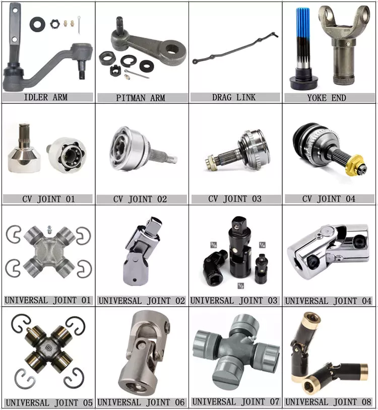
Hur hanterar drivaxlar variationer i hastighet och vridmoment under drift?
Drivaxlar är konstruerade för att hantera variationer i hastighet och vridmoment under drift genom att använda specifika mekanismer och konfigurationer. Dessa mekanismer gör det möjligt för drivaxlarna att anpassa sig till de förändrade kraven från kraftöverföring samtidigt som de bibehåller en smidig och effektiv drift. Här är en detaljerad förklaring av hur drivaxlar hanterar variationer i hastighet och vridmoment:
1. Flexibla kopplingar:
Drivaxlar har ofta flexibla kopplingar, såsom universalkopplingar (U-kopplingar) eller konstanthastighetskopplingar (CV-kopplingar), för att hantera variationer i hastighet och vridmoment. Dessa kopplingar ger flexibilitet och gör att drivaxeln kan överföra kraft även när de drivande och drivna komponenterna inte är perfekt justerade. U-kopplingar består av två ok som är sammankopplade med ett korsformat lager, vilket möjliggör vinkelrörelse mellan drivaxelsektionerna. Denna flexibilitet hanterar variationer i hastighet och vridmoment och kompenserar för feljustering. CV-kopplingar, som vanligtvis används i fordonsdrivaxlar, bibehåller en konstant rotationshastighet samtidigt som de hanterar förändrade arbetsvinklar. Dessa flexibla kopplingar möjliggör jämn kraftöverföring och minskar vibrationer och slitage orsakat av variationer i hastighet och vridmoment.
2. Glidfogar:
I vissa drivaxelkonstruktioner används glidleder för att hantera längdvariationer och avståndsförändringar mellan drivande och drivna komponenter. En glidled består av en inre och yttre rörformig sektion med splines eller en teleskopmekanism. När drivaxelns längd förändras på grund av fjädringens rörelser eller andra faktorer, tillåter glidleden axeln att förlängas eller komprimeras utan att påverka kraftöverföringen. Genom att tillåta axiell rörelse hjälper glidleder till att förhindra kärvning eller överdriven belastning på drivaxeln vid variationer i hastighet och vridmoment, vilket säkerställer smidig drift.
3. Balansering:
Drivaxlar balanseras för att optimera prestandan och minimera vibrationer orsakade av variationer i hastighet och vridmoment. Obalanser i drivaxeln kan leda till vibrationer, vilket inte bara påverkar komforten för fordonspassagerarna utan också ökar slitaget på axeln och dess tillhörande komponenter. Balansering innebär att omfördela massan längs drivaxeln för att uppnå jämn viktfördelning, vilket minskar vibrationer och förbättrar den totala prestandan. Dynamisk balansering, som vanligtvis innebär att man lägger till eller tar bort små vikter, säkerställer att drivaxeln fungerar smidigt även under varierande hastigheter och momentbelastningar.
4. Materialval och design:
Materialval och konstruktion av drivaxlar spelar en avgörande roll för att hantera variationer i hastighet och vridmoment. Drivaxlar är vanligtvis tillverkade av höghållfasta material, såsom stål eller aluminiumlegeringar, valda för sin förmåga att motstå de krafter och påfrestningar som är förknippade med varierande driftsförhållanden. Drivaxelns diameter och väggtjocklek bestäms också noggrant för att säkerställa tillräcklig styrka och styvhet. Dessutom inkluderar konstruktionen hänsyn till faktorer som kritisk hastighet, vridstyvhet och resonansundvikning, vilket bidrar till att bibehålla stabilitet och prestanda under hastighets- och vridmomentvariationer.
5. Smörjning:
Korrekt smörjning är avgörande för att drivaxlar ska kunna hantera variationer i hastighet och vridmoment. Smörjning av leder, såsom kardanleder eller CV-leder, minskar friktion och värme som genereras under drift, vilket säkerställer jämn rörelse och minimerar slitage. Tillräcklig smörjning hjälper också till att förhindra att komponenterna binder, vilket gör att drivaxeln kan hantera hastighets- och vridmomentvariationer mer effektivt. Regelbundet smörjunderhåll är nödvändigt för att säkerställa optimal prestanda och förlänga drivaxelns livslängd.
6. Systemövervakning:
Att övervaka drivaxelsystemets prestanda är viktigt för att identifiera eventuella problem relaterade till variationer i hastighet och vridmoment. Ovanliga vibrationer, ljud eller förändringar i kraftöverföringen kan indikera potentiella problem med drivaxeln. Regelbundna inspektioner och underhållskontroller möjliggör tidig upptäckt och åtgärd av problem, vilket hjälper till att förhindra ytterligare skador och säkerställa att drivaxeln fortsätter att hantera hastighets- och vridmomentvariationer effektivt.
Sammanfattningsvis hanterar drivaxlar variationer i hastighet och vridmoment under drift genom användning av flexibla kopplingar, glidförbindningar, balanseringsprocedurer, lämpligt materialval och design, smörjning och systemövervakning. Dessa mekanismer och metoder gör det möjligt för drivaxeln att hantera feljustering, längdförändringar och variationer i effektbehov, vilket säkerställer effektiv kraftöverföring, smidig drift och minskat slitage i olika applikationer.

How do drive shafts handle variations in load and vibration during operation?
Drive shafts are designed to handle variations in load and vibration during operation by employing various mechanisms and features. These mechanisms help ensure smooth power transmission, minimize vibrations, and maintain the structural integrity of the drive shaft. Here’s a detailed explanation of how drive shafts handle load and vibration variations:
1. Material Selection and Design:
Drive shafts are typically made from materials with high strength and stiffness, such as steel alloys or composite materials. The material selection and design take into account the anticipated loads and operating conditions of the application. By using appropriate materials and optimizing the design, drive shafts can withstand the expected variations in load without experiencing excessive deflection or deformation.
2. Torque Capacity:
Drive shafts are designed with a specific torque capacity that corresponds to the expected loads. The torque capacity takes into account factors such as the power output of the driving source and the torque requirements of the driven components. By selecting a drive shaft with sufficient torque capacity, variations in load can be accommodated without exceeding the drive shaft’s limits and risking failure or damage.
3. Dynamic Balancing:
During the manufacturing process, drive shafts can undergo dynamic balancing. Imbalances in the drive shaft can result in vibrations during operation. Through the balancing process, weights are strategically added or removed to ensure that the drive shaft spins evenly and minimizes vibrations. Dynamic balancing helps to mitigate the effects of load variations and reduces the potential for excessive vibrations in the drive shaft.
4. Dampers and Vibration Control:
Drive shafts can incorporate dampers or vibration control mechanisms to further minimize vibrations. These devices are typically designed to absorb or dissipate vibrations that may arise from load variations or other factors. Dampers can be in the form of torsional dampers, rubber isolators, or other vibration-absorbing elements strategically placed along the drive shaft. By managing and attenuating vibrations, drive shafts ensure smooth operation and enhance overall system performance.
5. CV Joints:
Constant Velocity (CV) joints are often used in drive shafts to accommodate variations in operating angles and to maintain a constant speed. CV joints allow the drive shaft to transmit power even when the driving and driven components are at different angles. By accommodating variations in operating angles, CV joints help minimize the impact of load variations and reduce potential vibrations that may arise from changes in the driveline geometry.
6. Lubrication and Maintenance:
Proper lubrication and regular maintenance are essential for drive shafts to handle load and vibration variations effectively. Lubrication helps reduce friction between moving parts, minimizing wear and heat generation. Regular maintenance, including inspection and lubrication of joints, ensures that the drive shaft remains in optimal condition, reducing the risk of failure or performance degradation due to load variations.
7. Structural Rigidity:
Drive shafts are designed to have sufficient structural rigidity to resist bending and torsional forces. This rigidity helps maintain the integrity of the drive shaft when subjected to load variations. By minimizing deflection and maintaining structural integrity, the drive shaft can effectively transmit power and handle variations in load without compromising performance or introducing excessive vibrations.
8. Control Systems and Feedback:
In some applications, drive shafts may be equipped with control systems that actively monitor and adjust parameters such as torque, speed, and vibration. These control systems use sensors and feedback mechanisms to detect variations in load or vibrations and make real-time adjustments to optimize performance. By actively managing load variations and vibrations, drive shafts can adapt to changing operating conditions and maintain smooth operation.
In summary, drive shafts handle variations in load and vibration during operation through careful material selection and design, torque capacity considerations, dynamic balancing, integration of dampers and vibration control mechanisms, utilization of CV joints, proper lubrication and maintenance, structural rigidity, and, in some cases, control systems and feedback mechanisms. By incorporating these features and mechanisms, drive shafts ensure reliable and efficient power transmission while minimizing the impact of load variations and vibrations on overall system performance.
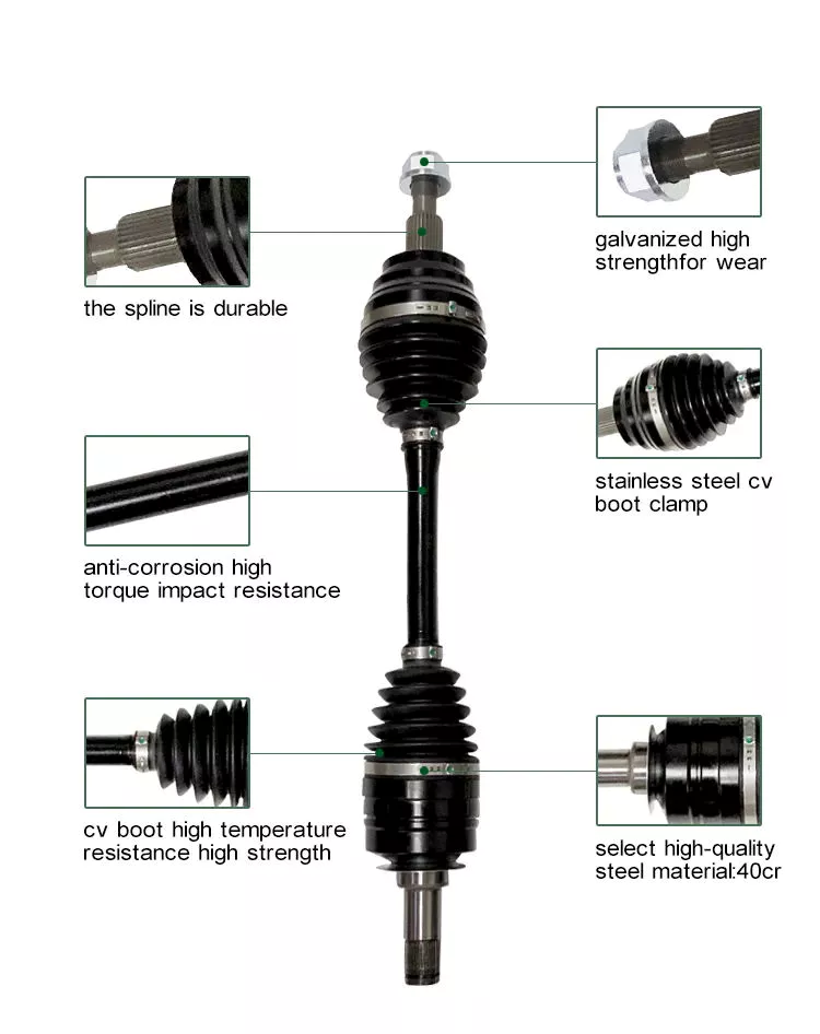
Can you explain the different types of drive shafts and their specific applications?
Drive shafts come in various types, each designed to suit specific applications and requirements. The choice of drive shaft depends on factors such as the type of vehicle or equipment, power transmission needs, space limitations, and operating conditions. Here’s an explanation of the different types of drive shafts and their specific applications:
1. Solid Shaft:
A solid shaft, also known as a one-piece or solid-steel drive shaft, is a single, uninterrupted shaft that runs from the engine or power source to the driven components. It is a simple and robust design used in many applications. Solid shafts are commonly found in rear-wheel-drive vehicles, where they transmit power from the transmission to the rear axle. They are also used in industrial machinery, such as pumps, generators, and conveyors, where a straight and rigid power transmission is required.
2. Tubular Shaft:
Tubular shafts, also called hollow shafts, are drive shafts with a cylindrical tube-like structure. They are constructed with a hollow core and are typically lighter than solid shafts. Tubular shafts offer benefits such as reduced weight, improved torsional stiffness, and better damping of vibrations. They find applications in various vehicles, including cars, trucks, and motorcycles, as well as in industrial equipment and machinery. Tubular drive shafts are commonly used in front-wheel-drive vehicles, where they connect the transmission to the front wheels.
3. Constant Velocity (CV) Shaft:
Constant Velocity (CV) shafts are specifically designed to handle angular movement and maintain a constant velocity between the engine/transmission and the driven components. They incorporate CV joints at both ends, which allow flexibility and compensation for changes in angle. CV shafts are commonly used in front-wheel-drive and all-wheel-drive vehicles, as well as in off-road vehicles and certain heavy machinery. The CV joints enable smooth power transmission even when the wheels are turned or the suspension moves, reducing vibrations and improving overall performance.
4. Slip Joint Shaft:
Slip joint shafts, also known as telescopic shafts, consist of two or more tubular sections that can slide in and out of each other. This design allows for length adjustment, accommodating changes in distance between the engine/transmission and the driven components. Slip joint shafts are commonly used in vehicles with long wheelbases or adjustable suspension systems, such as some trucks, buses, and recreational vehicles. By providing flexibility in length, slip joint shafts ensure a constant power transfer, even when the vehicle chassis experiences movement or changes in suspension geometry.
5. Double Cardan Shaft:
A double Cardan shaft, also referred to as a double universal joint shaft, is a type of drive shaft that incorporates two universal joints. This configuration helps to reduce vibrations and minimize the operating angles of the joints, resulting in smoother power transmission. Double Cardan shafts are commonly used in heavy-duty applications, such as trucks, off-road vehicles, and agricultural machinery. They are particularly suitable for applications with high torque requirements and large operating angles, providing enhanced durability and performance.
6. Composite Shaft:
Composite shafts are made from composite materials such as carbon fiber or fiberglass, offering advantages such as reduced weight, improved strength, and resistance to corrosion. Composite drive shafts are increasingly being used in high-performance vehicles, sports cars, and racing applications, where weight reduction and enhanced power-to-weight ratio are critical. The composite construction allows for precise tuning of stiffness and damping characteristics, resulting in improved vehicle dynamics and drivetrain efficiency.
7. PTO Shaft:
Power Take-Off (PTO) shafts are specialized drive shafts used in agricultural machinery and certain industrial equipment. They are designed to transfer power from the engine or power source to various attachments, such as mowers, balers, or pumps. PTO shafts typically have a splined connection at one end to connect to the power source and a universal joint at the other end to accommodate angular movement. They are characterized by their ability to transmit high torque levels and their compatibility with a range of driven implements.
8. Marine Shaft:
Marine shafts, also known as propeller shafts or tail shafts, are specifically designed for marine vessels. They transmit power from the engine to the propeller, enabling propulsion. Marine shafts are usually long and operate in a harsh environment, exposed to water, corrosion, and high torque loads. They are typically made of stainless steel or other corrosion-resistant materials and are designed to withstand the challenging conditions encountered in marine applications.
It’simportant to note that the specific applications of drive shafts may vary depending on the vehicle or equipment manufacturer, as well as the specific design and engineering requirements. The examples provided above highlight common applications for each type of drive shaft, but there may be additional variations and specialized designs based on specific industry needs and technological advancements.


editor by CX 2024-03-13