Product Description
Company Profile
Workshop
Detailed Photos
Product Description
| Material | Alloy Steel, Copper alloy(brass,silicon bronze,phosphor bronze,aluminum bronze,beryllium copper),Stainless Steel,Aluminum,Titanium, Magnesium, Superalloys,Molybdenum, Invar,,Zinc,Tungsten steel,incoloy,Nickel 200,Hastelloy, Inconel,Monel,ABS, PEEK,PTFE,PVC,Acetal. |
| Surface Treatment | Zn-plating, Ni-plating, Cr-plating, Tin-plating, copper-plating, the wreath oxygen resin spraying, the heat disposing, hot-dip galvanizing, black oxide coating, painting, powdering, color zinc-plated, blue black zinc-plated, rust preventive oil, titanium alloy galvanized, silver plating, plastic, electroplating, anodizing etc. |
| Producing Equipment | CNC machine,automatic lathe machine,CNC milling machine,lasering,tag grinding machine etc. |
| Drawing Format | Pro/E, Auto CAD, CZPT Works, UG, CAD/CAM, PDF |
| Managing Returned Goods | With quality problem or deviation from drawings |
| Warranty | Replacement at all our cost for rejected products |
| Main Markets | North America, South America, Eastern Europe , West Europe , North Europe, South Europe, Asia |
| How to order | * You send us drawing or sample |
| * We carry through project assessment | |
| * We make the sample and send it to you after you confirmed our design | |
| * You confirm the sample then place an order and pay us 30% deposit | |
| * We start producing | |
| * When the goods is done, you pay us the balance after you confirmed pictures or tracking numbers. | |
| * Trade is done, thank you!! |
Quality Control
Packaging & Shipping
Customer Reviews
FAQ
Q1:What kind of information do you need for quotation?
A: You can provide 2D/3D drawing or send your sample to our factory, then we can make according to your sample.
Q2: Can we CZPT NDA?
A: Sure. We can CZPT the NDA before got your drawings.
Q3: Do you provide sample?
A: Yes, we can provide you sample before mass order.
Q4: How can you ensure the quality?
A: We have profesional QC,IQC, OQC to guarantee the quality.
Q5: Delivery time?
A: For samples genearlly need 25 days. Mass production: around 30~45 days after receipt of deposit (Accurate delivery time
depends on specific items and quantities)
Q6: How about the transportation?
A: You can choose any mode of transportation you want, sea delivery, air delivery or door to door express.
/* March 10, 2571 17:59:20 */!function(){function s(e,r){var a,o={};try{e&&e.split(“,”).forEach(function(e,t){e&&(a=e.match(/(.*?):(.*)$/))&&1
| Material: | Alloy Steel |
|---|---|
| Load: | Drive Shaft |
| Stiffness & Flexibility: | Stiffness / Rigid Axle |
| Journal Diameter Dimensional Accuracy: | IT6-IT9 |
| Axis Shape: | Straight Shaft |
| Shaft Shape: | Real Axis |
| Customization: |
Available
| Customized Request |
|---|

How do drive shafts ensure efficient power transfer while maintaining balance?
Drive shafts employ various mechanisms to ensure efficient power transfer while maintaining balance. Efficient power transfer refers to the ability of the drive shaft to transmit rotational power from the source (such as an engine) to the driven components (such as wheels or machinery) with minimal energy loss. Balancing, on the other hand, involves minimizing vibrations and eliminating any uneven distribution of mass that can cause disturbances during operation. Here’s an explanation of how drive shafts achieve both efficient power transfer and balance:
1. Material Selection:
The material selection for drive shafts is crucial for maintaining balance and ensuring efficient power transfer. Drive shafts are commonly made from materials such as steel or aluminum alloys, chosen for their strength, stiffness, and durability. These materials have excellent dimensional stability and can withstand the torque loads encountered during operation. By using high-quality materials, drive shafts can minimize deformation, flexing, and imbalances that could compromise power transmission and generate vibrations.
2. Design Considerations:
The design of the drive shaft plays a significant role in both power transfer efficiency and balance. Drive shafts are engineered to have appropriate dimensions, including diameter and wall thickness, to handle the anticipated torque loads without excessive deflection or vibration. The design also considers factors such as the length of the drive shaft, the number and type of joints (such as universal joints or constant velocity joints), and the use of balancing weights. By carefully designing the drive shaft, manufacturers can achieve optimal power transfer efficiency while minimizing the potential for imbalance-induced vibrations.
3. Balancing Techniques:
Balance is crucial for drive shafts as any imbalance can cause vibrations, noise, and accelerated wear. To maintain balance, drive shafts undergo various balancing techniques during the manufacturing process. Static and dynamic balancing methods are employed to ensure that the mass distribution along the drive shaft is uniform. Static balancing involves adding counterweights at specific locations to offset any weight imbalances. Dynamic balancing is performed by spinning the drive shaft at high speeds and measuring any vibrations. If imbalances are detected, additional adjustments are made to achieve a balanced state. These balancing techniques help minimize vibrations and ensure smooth operation of the drive shaft.
4. Universal Joints and Constant Velocity Joints:
Drive shafts often incorporate universal joints (U-joints) or constant velocity (CV) joints to accommodate misalignment and maintain balance during operation. U-joints are flexible joints that allow for angular movement between shafts. They are typically used in applications where the drive shaft operates at varying angles. CV joints, on the other hand, are designed to maintain a constant velocity of rotation and are commonly used in front-wheel-drive vehicles. By incorporating these joints, drive shafts can compensate for misalignment, reduce stress on the shaft, and minimize vibrations that can negatively impact power transfer efficiency and balance.
5. Maintenance and Inspection:
Regular maintenance and inspection of drive shafts are essential for ensuring efficient power transfer and balance. Periodic checks for wear, damage, or misalignment can help identify any issues that may affect the drive shaft’s performance. Lubrication of the joints and proper tightening of fasteners are also critical for maintaining optimal operation. By adhering to recommended maintenance procedures, any imbalances or inefficiencies can be addressed promptly, ensuring continued efficient power transfer and balance.
In summary, drive shafts ensure efficient power transfer while maintaining balance through careful material selection, thoughtful design considerations, balancing techniques, and the incorporation of flexible joints. By optimizing these factors, drive shafts can transmit rotational power smoothly and reliably, minimizing energy losses and vibrations that can impact performance and longevity.

Can you provide real-world examples of vehicles and machinery that use drive shafts?
Drive shafts are widely used in various vehicles and machinery to transmit power from the engine or power source to the wheels or driven components. Here are some real-world examples of vehicles and machinery that utilize drive shafts:
1. Automobiles:
Drive shafts are commonly found in automobiles, especially those with rear-wheel drive or four-wheel drive systems. In these vehicles, the drive shaft transfers power from the transmission or transfer case to the rear differential or front differential, respectively. This allows the engine’s power to be distributed to the wheels, propelling the vehicle forward.
2. Trucks and Commercial Vehicles:
Drive shafts are essential components in trucks and commercial vehicles. They are used to transfer power from the transmission or transfer case to the rear axle or multiple axles in the case of heavy-duty trucks. Drive shafts in commercial vehicles are designed to handle higher torque loads and are often larger and more robust than those used in passenger cars.
3. Construction and Earthmoving Equipment:
Various types of construction and earthmoving equipment, such as excavators, loaders, bulldozers, and graders, rely on drive shafts for power transmission. These machines typically have complex drivetrain systems that use drive shafts to transfer power from the engine to the wheels or tracks, enabling them to perform heavy-duty tasks on construction sites or in mining operations.
4. Agricultural Machinery:
Agricultural machinery, including tractors, combines, and harvesters, utilize drive shafts to transmit power from the engine to the wheels or driven components. Drive shafts in agricultural machinery are often subjected to demanding conditions and may have additional features such as telescopic sections to accommodate variable distances between components.
5. Industrial Machinery:
Industrial machinery, such as manufacturing equipment, generators, pumps, and compressors, often incorporate drive shafts in their power transmission systems. These drive shafts transfer power from electric motors, engines, or other power sources to various driven components, enabling the machinery to perform specific tasks in industrial settings.
6. Marine Vessels:
In marine applications, drive shafts are commonly used to transmit power from the engine to the propeller in boats, ships, and other watercraft. Marine drive shafts are typically longer and designed to withstand the unique challenges posed by water environments, including corrosion resistance and appropriate sealing mechanisms.
7. Recreational Vehicles (RVs) and Motorhomes:
RVs and motorhomes often employ drive shafts as part of their drivetrain systems. These drive shafts transfer power from the transmission to the rear axle, allowing the vehicle to move and providing propulsion. Drive shafts in RVs may have additional features such as dampers or vibration-reducing components to enhance comfort during travel.
8. Off-Road and Racing Vehicles:
Off-road vehicles, such as SUVs, trucks, and all-terrain vehicles (ATVs), as well as racing vehicles, frequently utilize drive shafts. These drive shafts are designed to withstand the rigors of off-road conditions or high-performance racing, transmitting power efficiently to the wheels and ensuring optimal traction and performance.
9. Railway Rolling Stock:
In railway systems, drive shafts are employed in locomotives and some types of rolling stock. They transfer power from the locomotive’s engine to the wheels or propulsion system, enabling the train to move along the tracks. Railway drive shafts are typically much longer and may have additional features to accommodate the articulated or flexible nature of some train configurations.
10. Wind Turbines:
Large-scale wind turbines used for generating electricity incorporate drive shafts in their power transmission systems. The drive shafts transfer rotational energy from the turbine’s blades to the generator, where it is converted into electrical power. Drive shafts in wind turbines are designed to handle the significant torque and rotational forces generated by the wind.
These examples demonstrate the broad range of vehicles and machinery that rely on drive shafts for efficient power transmission and propulsion. Drive shafts are essential components in various industries, enabling the transfer of power from the source to the driven components, ultimately facilitating movement, operation, or the performance of specific tasks.
What benefits do drive shafts offer for different types of vehicles and equipment?
Drive shafts offer several benefits for different types of vehicles and equipment. They play a crucial role in power transmission and contribute to the overall performance, efficiency, and functionality of various systems. Here’s a detailed explanation of the benefits that drive shafts provide:
1. Efficient Power Transmission:
Drive shafts enable efficient power transmission from the engine or power source to the wheels or driven components. By connecting the engine or motor to the driven system, drive shafts efficiently transfer rotational power, allowing vehicles and equipment to perform their intended functions. This efficient power transmission ensures that the power generated by the engine is effectively utilized, optimizing the overall performance and productivity of the system.
2. Versatility:
Drive shafts offer versatility in their applications. They are used in various types of vehicles, including cars, trucks, motorcycles, and off-road vehicles. Additionally, drive shafts are employed in a wide range of equipment and machinery, such as agricultural machinery, construction equipment, industrial machinery, and marine vessels. The ability to adapt to different types of vehicles and equipment makes drive shafts a versatile component for power transmission.
3. Torque Handling:
Drive shafts are designed to handle high levels of torque. Torque is the rotational force generated by the engine or power source. Drive shafts are engineered to efficiently transmit this torque without excessive twisting or bending. By effectively handling torque, drive shafts ensure that the power generated by the engine is reliably transferred to the wheels or driven components, enabling vehicles and equipment to overcome resistance, such as heavy loads or challenging terrains.
4. Flexibility and Compensation:
Drive shafts provide flexibility and compensation for angular movement and misalignment. In vehicles, drive shafts accommodate the movement of the suspension system, allowing the wheels to move up and down independently. This flexibility ensures a constant power transfer even when the vehicle encounters uneven terrain. Similarly, in machinery, drive shafts compensate for misalignment between the engine or motor and the driven components, ensuring smooth power transmission and preventing excessive stress on the drivetrain.
5. Weight Reduction:
Drive shafts contribute to weight reduction in vehicles and equipment. Compared to other forms of power transmission, such as belt drives or chain drives, drive shafts are typically lighter in weight. This reduction in weight helps improve fuel efficiency in vehicles and reduces the overall weight of equipment, leading to enhanced maneuverability and increased payload capacity. Additionally, lighter drive shafts contribute to a better power-to-weight ratio, resulting in improved performance and acceleration.
6. Durability and Longevity:
Drive shafts are designed to be durable and long-lasting. They are constructed using materials such as steel or aluminum, which offer high strength and resistance to wear and fatigue. Drive shafts undergo rigorous testing and quality control measures to ensure their reliability and longevity. Proper maintenance, including lubrication and regular inspections, further enhances their durability. The robust construction and long lifespan of drive shafts contribute to the overall reliability and cost-effectiveness of vehicles and equipment.
7. Safety:
Drive shafts incorporate safety features to protect operators and bystanders. In vehicles, drive shafts are often enclosed within a protective tube or housing, preventing contact with moving parts and reducing the risk of injury in the event of a failure. Similarly, in machinery, safety shields or guards are commonly installed around exposed drive shafts to minimize the potential hazards associated with rotating components. These safety measures ensure the well-being of individuals operating or working in proximity to vehicles and equipment.
In summary, drive shafts offer several benefits for different types of vehicles and equipment. They enable efficient power transmission, provide versatility in various applications, handle torque effectively, offer flexibility and compensation, contribute to weight reduction, ensure durability and longevity, and incorporate safety features. By providing these advantages, drive shafts enhance the performance, efficiency, reliability, and safety of vehicles and equipment across a wide range of industries.


editor by CX 2024-02-17
China manufacturer OEM/ODM Service Precision CNC Machining Stainless Steel Automatic Lathe Turning CNC Machined Pto Shaft for Automation Printers
Product Description
|
Material |
1) Aluminum: AL 6061-T6, 6063, 7075-T etc. |
|
2) Stainless steel: 303,304,316L, 17-4(SUS630) etc. |
|
|
3) Steel: 4140, Q235, Q345B,20#,45# etc. |
|
|
4) Titanium: TA1,TA2/GR2, TA4/GR5, TC4, TC18 etc. |
|
|
5) Brass: C36000 (HPb62), C37700 (HPb59), C26800 (H68), C22000(H90) etc. |
|
|
6) Copper, bronze, Magnesium alloy, Delrin, POM,Acrylic, PC, etc. |
|
|
Finish |
Sandblasting, Anodize color, Blackenning, Zinc/Nickl Plating, Polish. |
|
Power coating, Passivation PVD, Titanium Plating, Electrogalvanizing. |
|
|
Electroplating chromium, electrophoresis, QPQ(Quench-Polish-Quench). |
|
|
Electro Polishing,Chrome Plating, Knurl, Laser etch Logo, etc. |
|
|
Main Equipment |
CNC Machining center(Milling), CNC Lathe, Grinding machine. |
|
Cylindrical grinder machine, Drilling machine, Laser Cutting Machine,etc. |
|
|
Drawing format |
STEP,STP,GIS,CAD,PDF,DWG,DXF etc or samples. |
|
Tolerance |
+/-0.01mm ~ +/-0.05mm |
|
Surface roughness |
Ra 0.1~3.2 |
|
Inspection |
Complete inspection lab with Micrometer, Optical Comparator, Caliper Vernier,CMM. |
|
Depth Caliper Vernier, Universal Protractor, Clock Gauge, Internal Centigrade Gauge. |
|
|
Capacity |
CNC turning work range: φ0.5mm-φ150mm*300mm. |
|
CNC milling work range: 510mm*1571mm*500mm. |
/* March 10, 2571 17:59:20 */!function(){function s(e,r){var a,o={};try{e&&e.split(“,”).forEach(function(e,t){e&&(a=e.match(/(.*?):(.*)$/))&&1
| Application: | Fastener, Auto and Motorcycle Accessory, Hardware Tool, Machinery Accessory |
|---|---|
| Standard: | GB, EN, API650, China GB Code, JIS Code, TEMA, ASME |
| Surface Treatment: | Anodizing |
| Production Type: | Mass Production |
| Machining Method: | CNC Machining |
| Material: | Nylon, Steel, Plastic, Brass, Alloy, Copper, Aluminum, Iron |
| Samples: |
US$ 20/Piece
1 Piece(Min.Order) | |
|---|
| Customization: |
Available
| Customized Request |
|---|

How do manufacturers ensure the compatibility of PTO shafts with different equipment?
Manufacturers employ various measures to ensure the compatibility of PTO (Power Take-Off) shafts with different equipment. Compatibility is crucial to ensure that PTO shafts can effectively transfer power from the power source to the driven machinery without compromising performance, safety, or ease of use. Here’s a detailed explanation of how manufacturers ensure compatibility:
1. Standardization: PTO shafts are designed and manufactured based on standardized specifications. These specifications outline the essential parameters such as shaft dimensions, spline sizes, torque ratings, and safety requirements. By adhering to standardized designs, manufacturers ensure that PTO shafts are compatible with a wide range of equipment that meets the same standards. Standardization allows for interchangeability, meaning that PTO shafts from one manufacturer can be used with equipment from another manufacturer as long as they conform to the same specifications.
2. Collaboration with Equipment Manufacturers: PTO shaft manufacturers often collaborate closely with equipment manufacturers to ensure compatibility. They work together to understand the specific requirements of the equipment and design PTO shafts that seamlessly integrate with the machinery. This collaboration may involve sharing technical specifications, conducting joint testing, and exchanging feedback. By working in partnership, manufacturers can address any compatibility issues early in the design and development process, resulting in PTO shafts that are tailored to the equipment’s needs.
3. Customization Options: PTO shaft manufacturers offer customization options to accommodate different equipment configurations. They provide flexibility in terms of shaft length, spline sizes, yoke designs, and coupling mechanisms. Equipment manufacturers can specify the required parameters, and the PTO shafts can be customized accordingly. This ensures that the PTO shafts precisely match the equipment’s power input/output requirements and connection methods, guaranteeing compatibility and efficient power transfer.
4. Testing and Validation: Manufacturers conduct rigorous testing and validation processes to ensure the compatibility and performance of PTO shafts. They subject the shafts to various tests, including torque testing, rotational speed testing, and durability testing. These tests verify that the PTO shafts can handle the expected power loads and operating conditions without failure. By validating the performance of the PTO shafts, manufacturers can ensure that they are compatible with a wide range of equipment and can reliably transfer power under different operating scenarios.
5. Compliance with Industry Standards: PTO shaft manufacturers adhere to industry standards and regulations to ensure compatibility. Organizations such as the American Society of Agricultural and Biological Engineers (ASABE) establish safety and performance standards for PTO shafts. Manufacturers design and produce their shafts in accordance with these standards, ensuring that their products meet the necessary requirements for compatibility and safety. Compliance with industry standards provides assurance to equipment manufacturers and end-users that the PTO shafts are compatible and suitable for use with different equipment.
6. Documentation and Guidelines: Manufacturers provide comprehensive documentation and guidelines to assist equipment manufacturers and end-users in ensuring compatibility. This documentation includes technical specifications, installation instructions, maintenance guidelines, and safety recommendations. The documentation helps equipment manufacturers select the appropriate PTO shaft for their equipment and provides guidance on proper installation and use. By following the manufacturer’s guidelines, equipment manufacturers can ensure compatibility and optimize the performance of the PTO shafts.
7. Ongoing Research and Development: PTO shaft manufacturers continuously invest in research and development to enhance compatibility with different equipment. They stay updated with industry trends, technological advancements, and evolving equipment requirements. This ongoing research and development enable manufacturers to improve the design, materials, and features of PTO shafts, ensuring compatibility with the latest equipment innovations and addressing any compatibility challenges that may arise.
By employing standardization, collaborating with equipment manufacturers, offering customization options, conducting thorough testing, complying with industry standards, providing documentation and guidelines, and investing in research and development, manufacturers ensure the compatibility of PTO shafts with different equipment. This compatibility allows for seamless integration, efficient power transfer, and optimal performance across a wide range of machinery and equipment in various industries.

Are there any limitations or disadvantages associated with PTO shafts?
While PTO (Power Take-Off) shafts offer numerous advantages in terms of power transfer and versatility, they also have certain limitations and disadvantages. It’s important to consider these factors when using PTO shafts to ensure safe and efficient operation. Here’s a detailed explanation of some limitations and disadvantages associated with PTO shafts:
1. Safety Hazards: One of the primary concerns with PTO shafts is the potential for safety hazards. PTO shafts rotate at high speeds and can pose a significant risk if not properly guarded or handled. Accidental contact with an exposed or inadequately shielded PTO shaft can result in severe injuries, including entanglement, amputation, or even fatalities. It is crucial to follow safety guidelines, implement proper guarding, and ensure that operators are well-trained on safe handling practices to mitigate these risks.
2. Maintenance and Lubrication: PTO shafts require regular maintenance and lubrication to ensure optimal performance and longevity. The moving parts, such as universal joints and splines, need to be inspected, cleaned, and lubricated at recommended intervals. Neglecting maintenance can lead to premature wear, decreased efficiency, and potential failures. Proper maintenance practices, including regular inspections and timely lubrication, are essential to mitigate these issues.
3. Alignment and Angles: PTO shafts rely on proper alignment and angles to ensure efficient power transfer. Misalignment or excessive angles between the power source and driven machinery can cause increased wear and strain on the components, leading to premature failure. Ensuring proper alignment and angle adjustment, using adjustable sliding yokes or other means, is important to prevent excessive stress on the PTO shaft and associated equipment.
4. Length Limitations: PTO shafts have limitations on their maximum and minimum length due to engineering constraints. The telescoping design allows for some adjustment, but there is a practical limit to how much the shaft can extend or retract. If the distance between the power source and driven machinery exceeds the maximum or falls below the minimum length of the PTO shaft, alternative solutions or modifications may be required. In some cases, additional components such as drive shaft extensions or gearboxes may be necessary to bridge the distance.
5. Compatibility: While manufacturers strive to ensure compatibility, there can still be challenges in finding the right PTO shaft for specific equipment configurations. Equipment may have unique requirements in terms of spline sizes, torque ratings, or connection methods that may not be readily available or compatible with off-the-shelf PTO shafts. Customization may be required to address these compatibility issues, which can result in increased costs or lead times.
6. Noise and Vibrations: PTO shafts in operation can generate significant noise and vibrations, especially at higher speeds. This can be a nuisance for operators and may require additional measures to reduce noise levels or dampen vibrations. Excessive vibrations can also affect the overall performance and lifespan of the PTO shaft and connected equipment. Implementing vibration dampeners or using flexible couplings can help mitigate these issues.
7. Power Limits: PTO shafts have specific power limits based on their design, materials, and components. Exceeding these power limits can lead to premature wear, component failures, or even shaft breakage. It is crucial to understand and adhere to the recommended power ratings for PTO shafts to ensure safe and reliable operation. In some cases, upgrading to a higher-capacity PTO shaft or implementing additional power transmission components may be necessary to accommodate higher power requirements.
8. Complex Installation and Removal: Installing and removing PTO shafts can be a complex process, especially in confined spaces or when dealing with heavy equipment. It may require aligning splines, engaging couplings, and securing locking mechanisms. Improper installation or removal techniques can lead to damage to the shaft or associated equipment. Proper training, handling equipment, and following manufacturer guidelines are essential to simplify and ensure the safe installation and removal of PTO shafts.
Despite these limitations and disadvantages, PTO shafts remain widely used and valuable components for power transfer in various industries. By addressing these considerations and implementing proper safety measures, maintenance practices, and alignment procedures, the potential drawbacks of PTO shafts can be effectively mitigated, allowing for safe and efficient operation.
What benefits do PTO shafts offer for various types of machinery?
PTO shafts (Power Take-Off shafts) offer several benefits for various types of machinery in agricultural and industrial applications. They provide a flexible and efficient means of power transmission, enabling machinery to perform specific tasks and functions. Here’s a detailed explanation of the benefits that PTO shafts offer for different types of machinery:
Versatility: PTO shafts contribute to the versatility of machinery by allowing them to be powered by a common power source, such as a tractor or an engine. This means that a single power source can be used to drive multiple implements or machines by simply connecting and disconnecting the PTO shaft. For example, in agriculture, a tractor equipped with a PTO shaft can power various implements such as mowers, balers, tillers, sprayers, and grain augers. Similarly, in industrial applications, PTO shafts enable the use of a single engine or motor to power different machines or equipment, such as generators, pumps, compressors, and industrial mixers.
Efficiency: PTO shafts offer an efficient method of power transfer from the power source to the machinery. By directly connecting the power source to the driven machine, PTO shafts minimize energy losses that may occur with other power transmission methods. This direct power transfer results in improved overall efficiency and performance of the machinery. Additionally, PTO shafts allow for the adjustment of rotational speed and power output to match the requirements of the specific machinery, ensuring optimal operation and reducing unnecessary energy consumption.
Cost Savings: The use of PTO shafts can lead to cost savings in multiple ways. Firstly, by utilizing a single power source to drive multiple machines or implements, the need for separate engines or motors for each piece of equipment is eliminated, reducing capital costs. Secondly, PTO shafts eliminate the requirement for additional fuel or energy sources, as they tap into the existing power source, resulting in lower fuel or energy expenses. Additionally, the versatility offered by PTO shafts allows for improved equipment utilization, maximizing the return on investment.
Flexibility: PTO shafts provide flexibility in terms of equipment setup and configuration. They can be adjusted in length or equipped with telescopic sections, allowing for easy adaptation to different equipment arrangements and varying distances between the power source and the driven machinery. This flexibility enables operators to quickly connect and disconnect the PTO shafts as needed, facilitating efficient equipment changes and reducing downtime. Moreover, the ability to adjust the rotational speed and power output of the PTO shafts adds further flexibility, accommodating the specific requirements of different machinery and applications.
Ease of Use: PTO shafts are relatively easy to use, making them accessible to operators with minimal training. The process of connecting and disconnecting the PTO shafts is straightforward, often involving a simple coupling or locking mechanism. This ease of use enhances equipment operability, allowing operators to quickly switch between different implements or machines without significant effort or time-consuming procedures. Furthermore, the direct power transfer through PTO shafts simplifies equipment operation, as the machinery can be powered by the existing power source without the need for additional controls or power management systems.
Increased Productivity: PTO shafts contribute to increased productivity in agricultural and industrial operations. By enabling the use of versatile machinery configurations, operators can perform a wide range of tasks using a single power source. This eliminates the need for manual labor or the use of multiple machines, streamlining workflow and reducing the time required to complete various operations. The efficiency and reliability of power transfer through PTO shafts also contribute to improved productivity by ensuring consistent and effective operation of machinery, resulting in enhanced output and reduced downtime.
Safety: While not directly related to machinery performance, PTO shafts also offer safety benefits. The implementation of safety shields or guards on PTO shafts helps prevent accidental contact with the rotating shaft, reducing the risk of injuries to operators. These safety features are designed to cover the rotating shaft and universal joints, ensuring that operators cannot come into contact with them during operation. Proper training on PTO shaft operation and adherence to safety guidelines further enhance operator safety when working with PTO-driven machinery.
In summary, PTO shafts offer a range of benefits for various types of machinery. These benefits include increased versatility, improved efficiency, cost savings, flexibility in equipment configurations, ease of use, increased productivity, and enhanced operator safety. PTO shafts play a crucial role in agricultural and industrial applications by enabling the direct power transfer from a common power source to different machines or implements, resulting in optimized performance and operational effectiveness.
editor by CX 2024-02-13
China OEM China Manufacturer Custom Lighting Turning Precision Stainless Steel Axle Stepped Drive Shaft with Mechanical Parts for Robot Vacuum and Motor
Product Description
Company Profile
—–ABOUT US—–
Focuses on the research, development, production, sales and service of fasteners, precision hardware parts and various metal products.
HangZhou CZPT CZPT Technology Co., Ltd. was established on March 1, 2016. It is located in Xihu (West Lake) Dis.ang District, HangZhou City, ZheJiang Province. It covers an area of 5600 square CZPT and focuses on the research, development, production, sales and service of fasteners, precision hardware parts and various metal products. The processed products are mainly cold heading, forging, precision turning, milling, assembly, stamping, supplemented by extrusion, upsetting and casting. In addition, we also have rich experience in anodizing, electroplating and heat treatment.
Product Parameters
| No. | Item | Specifications |
| 1 | Materials | Carbon steel: 12L15, 45#, 42CrMo; Stainless steel: 303, 304, 316, 420, 630; Aluminum alloy: 6061, 6063, 5052, 7075; Copper alloy: brass H58-H63, phosphor bronze, beryllium copper; Pure copper: T0 oxygen-free copper, T2 red copper; Plastics: nylon, bakelite, POM, PEEK; |
| 2 | Diameter | Ø0.3-Ø50 |
| 3 | Diameter tolerance | 0.005mm |
| 4 | Hardness: | HRC/HV |
| 5 | Length | 0.5mm-500mm |
| 6 | Heat treatment | Oil Quenching High frequency quenching Carburization Vacuum Heat treatment Mesh belt CZPT heat treatment |
| 7 | Surface treatment | Electrolytic plating (barrel plating, rack plating); Electroless plating (nickel plating); Ordinary sandblasting and anodizing (black, silver, gray, gold, red) Plastic spraying, spraying metal paint, etc.; |
Work Shop
Certifications
Research & Development
Development intervention
Development ability
Cost accounting
Quality control
Production feasibility assessment
Project landing
Assembly service
Complex project decomposition & optimization capabilities
Quick sample
Optimization of the mold plan for mass products
Product Category
Precision turning parts
Precision machining parts
Special requirements appearance parts
Presentative Brand
Why Choose Us?
Create value for customers
Support + Service + Made in China + Technological Innovation = Solution
★ Project management, solutions
★ Quickly designing and sampling
★ New product development, technological breakthrough
★ Component and machine assembly service
Engineering capabilities
★Development intervention
★Development ability
Cost accounting
Quality control
Production feasibility assessment
Project landing
Assembly service
★Complex project decomposition & optimization capabilities
★Quick sample
★Optimization of the mold plan for mass products /* March 10, 2571 17:59:20 */!function(){function s(e,r){var a,o={};try{e&&e.split(“,”).forEach(function(e,t){e&&(a=e.match(/(.*?):(.*)$/))&&1
| Material: | Alloy Steel |
|---|---|
| Load: | Drive Shaft |
| Stiffness & Flexibility: | Stiffness / Rigid Axle |
| Journal Diameter Dimensional Accuracy: | IT6-IT9 |
| Axis Shape: | Straight Shaft |
| Shaft Shape: | Stepped Shaft |
| Customization: |
Available
| Customized Request |
|---|
Are there any limitations or disadvantages associated with drive shafts?
While drive shafts are widely used and offer several advantages, they also have certain limitations and disadvantages that should be considered. Here’s a detailed explanation of the limitations and disadvantages associated with drive shafts:
1. Length and Misalignment Constraints:
Drive shafts have a maximum practical length due to factors such as material strength, weight considerations, and the need to maintain rigidity and minimize vibrations. Longer drive shafts can be prone to increased bending and torsional deflection, leading to reduced efficiency and potential driveline vibrations. Additionally, drive shafts require proper alignment between the driving and driven components. Misalignment can cause increased wear, vibrations, and premature failure of the drive shaft or its associated components.
2. Limited Operating Angles:
Drive shafts, especially those using U-joints, have limitations on operating angles. U-joints are typically designed to operate within specific angular ranges, and operating beyond these limits can result in reduced efficiency, increased vibrations, and accelerated wear. In applications requiring large operating angles, constant velocity (CV) joints are often used to maintain a constant speed and accommodate greater angles. However, CV joints may introduce higher complexity and cost compared to U-joints.
3. Maintenance Requirements:
Drive shafts require regular maintenance to ensure optimal performance and reliability. This includes periodic inspection, lubrication of joints, and balancing if necessary. Failure to perform routine maintenance can lead to increased wear, vibrations, and potential driveline issues. Maintenance requirements should be considered in terms of time and resources when using drive shafts in various applications.
4. Noise and Vibration:
Drive shafts can generate noise and vibrations, especially at high speeds or when operating at certain resonant frequencies. Imbalances, misalignment, worn joints, or other factors can contribute to increased noise and vibrations. These vibrations may affect the comfort of vehicle occupants, contribute to component fatigue, and require additional measures such as dampers or vibration isolation systems to mitigate their effects.
5. Weight and Space Constraints:
Drive shafts add weight to the overall system, which can be a consideration in weight-sensitive applications, such as automotive or aerospace industries. Additionally, drive shafts require physical space for installation. In compact or tightly packaged equipment or vehicles, accommodating the necessary drive shaft length and clearances can be challenging, requiring careful design and integration considerations.
6. Cost Considerations:
Drive shafts, depending on their design, materials, and manufacturing processes, can involve significant costs. Customized or specialized drive shafts tailored to specific equipment requirements may incur higher expenses. Additionally, incorporating advanced joint configurations, such as CV joints, can add complexity and cost to the drive shaft system.
7. Inherent Power Loss:
Drive shafts transmit power from the driving source to the driven components, but they also introduce some inherent power loss due to friction, bending, and other factors. This power loss can reduce overall system efficiency, particularly in long drive shafts or applications with high torque requirements. It is important to consider power loss when determining the appropriate drive shaft design and specifications.
8. Limited Torque Capacity:
While drive shafts can handle a wide range of torque loads, there are limits to their torque capacity. Exceeding the maximum torque capacity of a drive shaft can lead to premature failure, resulting in downtime and potential damage to other driveline components. It is crucial to select a drive shaft with sufficient torque capacity for the intended application.
Despite these limitations and disadvantages, drive shafts remain a widely used and effective means of power transmission in various industries. Manufacturers continuously work to address these limitations through advancements in materials, design techniques, joint configurations, and balancing processes. By carefully considering the specific application requirements and potential drawbacks, engineers and designers can mitigate the limitations and maximize the benefits of drive shafts in their respective systems.
Can drive shafts be customized for specific vehicle or equipment requirements?
Yes, drive shafts can be customized to meet specific vehicle or equipment requirements. Customization allows manufacturers to tailor the design, dimensions, materials, and other parameters of the drive shaft to ensure compatibility and optimal performance within a particular vehicle or equipment. Here’s a detailed explanation of how drive shafts can be customized:
1. Dimensional Customization:
Drive shafts can be customized to match the dimensional requirements of the vehicle or equipment. This includes adjusting the overall length, diameter, and spline configuration to ensure proper fitment and clearances within the specific application. By customizing the dimensions, the drive shaft can be seamlessly integrated into the driveline system without any interference or limitations.
2. Material Selection:
The choice of materials for drive shafts can be customized based on the specific requirements of the vehicle or equipment. Different materials, such as steel alloys, aluminum alloys, or specialized composites, can be selected to optimize strength, weight, and durability. The material selection can be tailored to meet the torque, speed, and operating conditions of the application, ensuring the drive shaft’s reliability and longevity.
3. Joint Configuration:
Drive shafts can be customized with different joint configurations to accommodate specific vehicle or equipment requirements. For example, universal joints (U-joints) may be suitable for applications with lower operating angles and moderate torque demands, while constant velocity (CV) joints are often used in applications requiring higher operating angles and smoother power transmission. The choice of joint configuration depends on factors such as operating angle, torque capacity, and desired performance characteristics.
4. Torque and Power Capacity:
Customization allows drive shafts to be designed with the appropriate torque and power capacity for the specific vehicle or equipment. Manufacturers can analyze the torque requirements, operating conditions, and safety margins of the application to determine the optimal torque rating and power capacity of the drive shaft. This ensures that the drive shaft can handle the required loads without experiencing premature failure or performance issues.
5. Balancing and Vibration Control:
Drive shafts can be customized with precision balancing and vibration control measures. Imbalances in the drive shaft can lead to vibrations, increased wear, and potential driveline issues. By employing dynamic balancing techniques during the manufacturing process, manufacturers can minimize vibrations and ensure smooth operation. Additionally, vibration dampers or isolation systems can be integrated into the drive shaft design to further mitigate vibrations and enhance overall system performance.
6. Integration and Mounting Considerations:
Customization of drive shafts takes into account the integration and mounting requirements of the specific vehicle or equipment. Manufacturers work closely with the vehicle or equipment designers to ensure that the drive shaft fits seamlessly into the driveline system. This includes adapting the mounting points, interfaces, and clearances to ensure proper alignment and installation of the drive shaft within the vehicle or equipment.
7. Collaboration and Feedback:
Manufacturers often collaborate with vehicle manufacturers, OEMs (Original Equipment Manufacturers), or end-users to gather feedback and incorporate their specific requirements into the drive shaft customization process. By actively seeking input and feedback, manufacturers can address specific needs, optimize performance, and ensure compatibility with the vehicle or equipment. This collaborative approach enhances the customization process and results in drive shafts that meet the exact requirements of the application.
8. Compliance with Standards:
Customized drive shafts can be designed to comply with relevant industry standards and regulations. Compliance with standards, such as ISO (International Organization for Standardization) or specific industry standards, ensures that the customized drive shafts meet quality, safety, and performance requirements. Adhering to these standards provides assurance that the drive shafts are compatible and can be seamlessly integrated into the specific vehicle or equipment.
In summary, drive shafts can be customized to meet specific vehicle or equipment requirements through dimensional customization, material selection, joint configuration, torque and power capacity optimization, balancing and vibration control, integration and mounting considerations, collaboration with stakeholders, and compliance with industry standards. Customization allows drive shafts to be precisely tailored to the needs of the application, ensuring compatibility, reliability, and optimal performance.

Are there variations in drive shaft designs for different types of machinery?
Yes, there are variations in drive shaft designs to cater to the specific requirements of different types of machinery. The design of a drive shaft is influenced by factors such as the application, power transmission needs, space limitations, operating conditions, and the type of driven components. Here’s an explanation of how drive shaft designs can vary for different types of machinery:
1. Automotive Applications:
In the automotive industry, drive shaft designs can vary depending on the vehicle’s configuration. Rear-wheel-drive vehicles typically use a single-piece or two-piece drive shaft, which connects the transmission or transfer case to the rear differential. Front-wheel-drive vehicles often use a different design, employing a drive shaft that combines with the constant velocity (CV) joints to transmit power to the front wheels. All-wheel-drive vehicles may have multiple drive shafts to distribute power to all wheels. The length, diameter, material, and joint types can differ based on the vehicle’s layout and torque requirements.
2. Industrial Machinery:
Drive shaft designs for industrial machinery depend on the specific application and power transmission requirements. In manufacturing machinery, such as conveyors, presses, and rotating equipment, drive shafts are designed to transfer power efficiently within the machine. They may incorporate flexible joints or use a splined or keyed connection to accommodate misalignment or allow for easy disassembly. The dimensions, materials, and reinforcement of the drive shaft are selected based on the torque, speed, and operating conditions of the machinery.
3. Agriculture and Farming:
Agricultural machinery, such as tractors, combines, and harvesters, often requires drive shafts that can handle high torque loads and varying operating angles. These drive shafts are designed to transmit power from the engine to attachments and implements, such as mowers, balers, tillers, and harvesters. They may incorporate telescopic sections to accommodate adjustable lengths, flexible joints to compensate for misalignment during operation, and protective shielding to prevent entanglement with crops or debris.
4. Construction and Heavy Equipment:
Construction and heavy equipment, including excavators, loaders, bulldozers, and cranes, require robust drive shaft designs capable of transmitting power in demanding conditions. These drive shafts often have larger diameters and thicker walls to handle high torque loads. They may incorporate universal joints or CV joints to accommodate operating angles and absorb shocks and vibrations. Drive shafts in this category may also have additional reinforcements to withstand the harsh environments and heavy-duty applications associated with construction and excavation.
5. Marine and Maritime Applications:
Drive shaft designs for marine applications are specifically engineered to withstand the corrosive effects of seawater and the high torque loads encountered in marine propulsion systems. Marine drive shafts are typically made from stainless steel or other corrosion-resistant materials. They may incorporate flexible couplings or dampening devices to reduce vibration and mitigate the effects of misalignment. The design of marine drive shafts also considers factors such as shaft length, diameter, and support bearings to ensure reliable power transmission in marine vessels.
6. Mining and Extraction Equipment:
In the mining industry, drive shafts are used in heavy machinery and equipment such as mining trucks, excavators, and drilling rigs. These drive shafts need to withstand extremely high torque loads and harsh operating conditions. Drive shaft designs for mining applications often feature larger diameters, thicker walls, and specialized materials such as alloy steel or composite materials. They may incorporate universal joints or CV joints to handle operating angles, and they are designed to be resistant to abrasion and wear.
These examples highlight the variations in drive shaft designs for different types of machinery. The design considerations take into account factors such as power requirements, operating conditions, space constraints, alignment needs, and the specific demands of the machinery or industry. By tailoring the drive shaft design to the unique requirements of each application, optimal power transmission efficiency and reliability can be achieved.
editor by CX 2023-12-25
China supplier CNC Turning Micro Shaft Durable Metal Transmission Shaft Customized Machining Drive Shaft
Product Description
Product Description
| Material | Aluminium Alloy,Carbon Steel,Stainless steel,Copper,Brass,Nylon,Plastic(Customized Material) |
| Producing Equipment | 3 Axis,4 Axis,5 Axis CNC Machines,Automatic Lathe Machines,Stamping Machines,CNC Milling machines,CNC Turning Machines,Turning Milling Compound Machines,Grinding Machines,Rolling Machines,Laser Machines. |
| Surface Treatment | Anodizing,Polishing,Electroplating,Heat Treatment,Spray Paint,Sand Blasting. |
| Testing Equipment | Salt Spray Test, Hardness Tester, Coating Thickness Tester, Two Dimensions Measuring Instrument. |
| Quality Testing | 100% Quality Inspection Before Shipment. |
| Lead Time | Generally, The Delivery Date Is 7-15 Days,Delivery Time of Bulk Order Is More Than 15 days. |
| Tolerance and Roughness | Size Tolerance:+/-0.005 – 0.01mm,Roughness: Ra0.2 – Ra3.2 (Custom Size Requirements) |
| Cargo Shipment | Express(DHL,Fedex,UPS, TNT ),Air shipment+Local Express Delivery,Ocean Shipment. |
| Main Markets | America, Europe, Australia, Asia. |
| Payment Type | T/T, L/C, Paypal,Western Union,Others. |
Packaging & Shipping
Company Profile
HangZhou Fuyouda Technology Co., Ltd. Was established in city known as the “world factory”-HangZhou. We are factory and have many kinds of machine, such as 5-axis CNC machines, lath machines, turning milling compound machines. After 10 years of R&D, production and sales, we have 80% market share in the field of 3D printer parts in China and we are specializing in CNC machinig for 10 years. We are committed to creating a work and production environment that is above the industry average. We adopt scientific production management methods to improve production efficiency and reduce production costs. Please believe and choose us! We adhere to the management principles of “Quality First, Customer first and Credit-based” since the establishment of the company and always do our best to satisfy potential needs of our customers. Our company is sincerely willing to cooperate with enterprises from all over the world in order to realize a CZPT situation since the trend of economic globalization has developed with anirresistible force.
Our Advantages
FAQ
| Application: | Machinery Accessory |
|---|---|
| Standard: | GB, EN |
| Surface Treatment: | Polishing |
| Production Type: | Mass Production |
| Machining Method: | CNC Turning |
| Material: | Stainless Steel |
| Samples: |
US$ 2.8/Piece
1 Piece(Min.Order) | |
|---|
| Customization: |
Available
| Customized Request |
|---|
Are there any limitations or disadvantages associated with drive shafts?
While drive shafts are widely used and offer several advantages, they also have certain limitations and disadvantages that should be considered. Here’s a detailed explanation of the limitations and disadvantages associated with drive shafts:
1. Length and Misalignment Constraints:
Drive shafts have a maximum practical length due to factors such as material strength, weight considerations, and the need to maintain rigidity and minimize vibrations. Longer drive shafts can be prone to increased bending and torsional deflection, leading to reduced efficiency and potential driveline vibrations. Additionally, drive shafts require proper alignment between the driving and driven components. Misalignment can cause increased wear, vibrations, and premature failure of the drive shaft or its associated components.
2. Limited Operating Angles:
Drive shafts, especially those using U-joints, have limitations on operating angles. U-joints are typically designed to operate within specific angular ranges, and operating beyond these limits can result in reduced efficiency, increased vibrations, and accelerated wear. In applications requiring large operating angles, constant velocity (CV) joints are often used to maintain a constant speed and accommodate greater angles. However, CV joints may introduce higher complexity and cost compared to U-joints.
3. Maintenance Requirements:
Drive shafts require regular maintenance to ensure optimal performance and reliability. This includes periodic inspection, lubrication of joints, and balancing if necessary. Failure to perform routine maintenance can lead to increased wear, vibrations, and potential driveline issues. Maintenance requirements should be considered in terms of time and resources when using drive shafts in various applications.
4. Noise and Vibration:
Drive shafts can generate noise and vibrations, especially at high speeds or when operating at certain resonant frequencies. Imbalances, misalignment, worn joints, or other factors can contribute to increased noise and vibrations. These vibrations may affect the comfort of vehicle occupants, contribute to component fatigue, and require additional measures such as dampers or vibration isolation systems to mitigate their effects.
5. Weight and Space Constraints:
Drive shafts add weight to the overall system, which can be a consideration in weight-sensitive applications, such as automotive or aerospace industries. Additionally, drive shafts require physical space for installation. In compact or tightly packaged equipment or vehicles, accommodating the necessary drive shaft length and clearances can be challenging, requiring careful design and integration considerations.
6. Cost Considerations:
Drive shafts, depending on their design, materials, and manufacturing processes, can involve significant costs. Customized or specialized drive shafts tailored to specific equipment requirements may incur higher expenses. Additionally, incorporating advanced joint configurations, such as CV joints, can add complexity and cost to the drive shaft system.
7. Inherent Power Loss:
Drive shafts transmit power from the driving source to the driven components, but they also introduce some inherent power loss due to friction, bending, and other factors. This power loss can reduce overall system efficiency, particularly in long drive shafts or applications with high torque requirements. It is important to consider power loss when determining the appropriate drive shaft design and specifications.
8. Limited Torque Capacity:
While drive shafts can handle a wide range of torque loads, there are limits to their torque capacity. Exceeding the maximum torque capacity of a drive shaft can lead to premature failure, resulting in downtime and potential damage to other driveline components. It is crucial to select a drive shaft with sufficient torque capacity for the intended application.
Despite these limitations and disadvantages, drive shafts remain a widely used and effective means of power transmission in various industries. Manufacturers continuously work to address these limitations through advancements in materials, design techniques, joint configurations, and balancing processes. By carefully considering the specific application requirements and potential drawbacks, engineers and designers can mitigate the limitations and maximize the benefits of drive shafts in their respective systems.

How do drive shafts contribute to the efficiency of vehicle propulsion and power transmission?
Drive shafts play a crucial role in the efficiency of vehicle propulsion and power transmission systems. They are responsible for transferring power from the engine or power source to the wheels or driven components. Here’s a detailed explanation of how drive shafts contribute to the efficiency of vehicle propulsion and power transmission:
1. Power Transfer:
Drive shafts transmit power from the engine or power source to the wheels or driven components. By efficiently transferring rotational energy, drive shafts enable the vehicle to move forward or drive the machinery. The design and construction of drive shafts ensure minimal power loss during the transfer process, maximizing the efficiency of power transmission.
2. Torque Conversion:
Drive shafts can convert torque from the engine or power source to the wheels or driven components. Torque conversion is necessary to match the power characteristics of the engine with the requirements of the vehicle or machinery. Drive shafts with appropriate torque conversion capabilities ensure that the power delivered to the wheels is optimized for efficient propulsion and performance.
3. Constant Velocity (CV) Joints:
Many drive shafts incorporate Constant Velocity (CV) joints, which help maintain a constant speed and efficient power transmission, even when the driving and driven components are at different angles. CV joints allow for smooth power transfer and minimize vibration or power losses that may occur due to changing operating angles. By maintaining constant velocity, drive shafts contribute to efficient power transmission and improved overall vehicle performance.
4. Lightweight Construction:
Efficient drive shafts are often designed with lightweight materials, such as aluminum or composite materials. Lightweight construction reduces the rotational mass of the drive shaft, which results in lower inertia and improved efficiency. Reduced rotational mass enables the engine to accelerate and decelerate more quickly, allowing for better fuel efficiency and overall vehicle performance.
5. Minimized Friction:
Efficient drive shafts are engineered to minimize frictional losses during power transmission. They incorporate features such as high-quality bearings, low-friction seals, and proper lubrication to reduce energy losses caused by friction. By minimizing friction, drive shafts enhance power transmission efficiency and maximize the available power for propulsion or operating other machinery.
6. Balanced and Vibration-Free Operation:
Drive shafts undergo dynamic balancing during the manufacturing process to ensure smooth and vibration-free operation. Imbalances in the drive shaft can lead to power losses, increased wear, and vibrations that reduce overall efficiency. By balancing the drive shaft, it can spin evenly, minimizing vibrations and optimizing power transmission efficiency.
7. Maintenance and Regular Inspection:
Proper maintenance and regular inspection of drive shafts are essential for maintaining their efficiency. Regular lubrication, inspection of joints and components, and prompt repair or replacement of worn or damaged parts help ensure optimal power transmission efficiency. Well-maintained drive shafts operate with minimal friction, reduced power losses, and improved overall efficiency.
8. Integration with Efficient Transmission Systems:
Drive shafts work in conjunction with efficient transmission systems, such as manual, automatic, or continuously variable transmissions. These transmissions help optimize power delivery and gear ratios based on driving conditions and vehicle speed. By integrating with efficient transmission systems, drive shafts contribute to the overall efficiency of the vehicle propulsion and power transmission system.
9. Aerodynamic Considerations:
In some cases, drive shafts are designed with aerodynamic considerations in mind. Streamlined drive shafts, often used in high-performance or electric vehicles, minimize drag and air resistance to improve overall vehicle efficiency. By reducing aerodynamic drag, drive shafts contribute to the efficient propulsion and power transmission of the vehicle.
10. Optimized Length and Design:
Drive shafts are designed to have optimal lengths and designs to minimize energy losses. Excessive drive shaft length or improper design can introduce additional rotational mass, increase bending stresses, and result in energy losses. By optimizing the length and design, drive shafts maximize power transmission efficiency and contribute to improved overall vehicle efficiency.
Overall, drive shafts contribute to the efficiency of vehicle propulsion and power transmission through effective power transfer, torque conversion, utilization of CV joints, lightweight construction, minimized friction, balanced operation, regular maintenance, integration with efficient transmission systems, aerodynamic considerations, and optimized length and design. By ensuring efficient power delivery and minimizing energy losses, drive shafts play a significant role in enhancing the overall efficiency and performance of vehicles and machinery.

Can you explain the different types of drive shafts and their specific applications?
Drive shafts come in various types, each designed to suit specific applications and requirements. The choice of drive shaft depends on factors such as the type of vehicle or equipment, power transmission needs, space limitations, and operating conditions. Here’s an explanation of the different types of drive shafts and their specific applications:
1. Solid Shaft:
A solid shaft, also known as a one-piece or solid-steel drive shaft, is a single, uninterrupted shaft that runs from the engine or power source to the driven components. It is a simple and robust design used in many applications. Solid shafts are commonly found in rear-wheel-drive vehicles, where they transmit power from the transmission to the rear axle. They are also used in industrial machinery, such as pumps, generators, and conveyors, where a straight and rigid power transmission is required.
2. Tubular Shaft:
Tubular shafts, also called hollow shafts, are drive shafts with a cylindrical tube-like structure. They are constructed with a hollow core and are typically lighter than solid shafts. Tubular shafts offer benefits such as reduced weight, improved torsional stiffness, and better damping of vibrations. They find applications in various vehicles, including cars, trucks, and motorcycles, as well as in industrial equipment and machinery. Tubular drive shafts are commonly used in front-wheel-drive vehicles, where they connect the transmission to the front wheels.
3. Constant Velocity (CV) Shaft:
Constant Velocity (CV) shafts are specifically designed to handle angular movement and maintain a constant velocity between the engine/transmission and the driven components. They incorporate CV joints at both ends, which allow flexibility and compensation for changes in angle. CV shafts are commonly used in front-wheel-drive and all-wheel-drive vehicles, as well as in off-road vehicles and certain heavy machinery. The CV joints enable smooth power transmission even when the wheels are turned or the suspension moves, reducing vibrations and improving overall performance.
4. Slip Joint Shaft:
Slip joint shafts, also known as telescopic shafts, consist of two or more tubular sections that can slide in and out of each other. This design allows for length adjustment, accommodating changes in distance between the engine/transmission and the driven components. Slip joint shafts are commonly used in vehicles with long wheelbases or adjustable suspension systems, such as some trucks, buses, and recreational vehicles. By providing flexibility in length, slip joint shafts ensure a constant power transfer, even when the vehicle chassis experiences movement or changes in suspension geometry.
5. Double Cardan Shaft:
A double Cardan shaft, also referred to as a double universal joint shaft, is a type of drive shaft that incorporates two universal joints. This configuration helps to reduce vibrations and minimize the operating angles of the joints, resulting in smoother power transmission. Double Cardan shafts are commonly used in heavy-duty applications, such as trucks, off-road vehicles, and agricultural machinery. They are particularly suitable for applications with high torque requirements and large operating angles, providing enhanced durability and performance.
6. Composite Shaft:
Composite shafts are made from composite materials such as carbon fiber or fiberglass, offering advantages such as reduced weight, improved strength, and resistance to corrosion. Composite drive shafts are increasingly being used in high-performance vehicles, sports cars, and racing applications, where weight reduction and enhanced power-to-weight ratio are critical. The composite construction allows for precise tuning of stiffness and damping characteristics, resulting in improved vehicle dynamics and drivetrain efficiency.
7. PTO Shaft:
Power Take-Off (PTO) shafts are specialized drive shafts used in agricultural machinery and certain industrial equipment. They are designed to transfer power from the engine or power source to various attachments, such as mowers, balers, or pumps. PTO shafts typically have a splined connection at one end to connect to the power source and a universal joint at the other end to accommodate angular movement. They are characterized by their ability to transmit high torque levels and their compatibility with a range of driven implements.
8. Marine Shaft:
Marine shafts, also known as propeller shafts or tail shafts, are specifically designed for marine vessels. They transmit power from the engine to the propeller, enabling propulsion. Marine shafts are usually long and operate in a harsh environment, exposed to water, corrosion, and high torque loads. They are typically made of stainless steel or other corrosion-resistant materials and are designed to withstand the challenging conditions encountered in marine applications.
It’simportant to note that the specific applications of drive shafts may vary depending on the vehicle or equipment manufacturer, as well as the specific design and engineering requirements. The examples provided above highlight common applications for each type of drive shaft, but there may be additional variations and specialized designs based on specific industry needs and technological advancements.
editor by CX 2023-11-20
China manufacturer Custom CNC Machining Turning Spline Bolt Nut Hollow Threaded Spindle Gear Steel Propeller Drive Shaft of Motorcycle Electric Motor Auto Generator Transmission
Product Description
| Basic Info. of Our Customized CNC Machining Parts | |
| Quotation | According To Your Drawings or Samples. (Size, Material, Thickness, Processing Content And Required Technology, etc.) |
| Tolerance | +/-0.005 – 0.01mm (Customizable) |
| Surface Roughness | Ra0.2 – Ra3.2 (Customizable) |
| Materials Available | Aluminum, Copper, Brass, Stainless Steel, Titanium, Iron, Plastic, Acrylic, PE, PVC, ABS, POM, PTFE etc. |
| Surface Treatment | Polishing, Surface Chamfering, Hardening and Tempering, Nickel plating, Chrome plating, zinc plating, Laser engraving, Sandblasting, Passivating, Clear Anodized, Color Anodized, Sandblast Anodized, Chemical Film, Brushing, etc. |
| Processing | Hot/Cold forging, Heat treatment, CNC Turning, Milling, Drilling and Tapping, Surface Treatment, Laser Cutting, Stamping, Die Casting, Injection Molding, etc. |
| Testing Equipment | Coordinate Measuring Machine (CMM) / Vernier Caliper/ / Automatic Height Gauge /Hardness Tester /Surface Roughness Teste/Run-out Instrument/Optical Projector, Micrometer/ Salt spray testing machine |
| Drawing Formats | PRO/E, Auto CAD, CZPT Works , UG, CAD / CAM / CAE, PDF |
| Our Advantages | 1.) 24 hours online service & quickly quote and delivery. 2.) 100% quality inspection (with Quality Inspection Report) before delivery. All our products are manufactured under ISO 9001:2015. 3.) A strong, professional and reliable technical team with 16+ years of manufacturing experience. 4.) We have stable supply chain partners, including raw material suppliers, bearing suppliers, forging plants, surface treatment plants, etc. 5.) We can provide customized assembly services for those customers who have assembly needs. |
| Available Material | |
| Stainless Steel | SS201,SS301, SS303, SS304, SS316, SS416, etc. |
| Steel | mild steel, Carbon steel, 4140, 4340, Q235, Q345B, 20#, 45#, etc. |
| Brass | HPb63, HPb62, HPb61, HPb59, H59, H62, H68, H80, etc. |
| Copper | C11000, C12000,C12000, C36000 etc. |
| Aluminum | A380, AL2571, AL6061, Al6063, AL6082, AL7075, AL5052, etc. |
| Iron | A36, 45#, 1213, 12L14, 1215 etc. |
| Plastic | ABS, PC, PE, POM, Delrin, Nylon, PP, PEI, Peek etc. |
| Others | Various types of Titanium alloy, Rubber, Bronze, etc. |
| Available Surface Treatment | |
| Stainless Steel | Polishing, Passivating, Sandblasting, Laser engraving, etc. |
| Steel | Zinc plating, Oxide black, Nickel plating, Chrome plating, Carburized, Powder Coated, etc. |
| Aluminum parts | Clear Anodized, Color Anodized, Sandblast Anodized, Chemical Film, Brushing, Polishing, etc. |
| Plastic | Plating gold(ABS), Painting, Brushing(Acylic), Laser engraving, etc. |
FAQ:
Q1: Are you a trading company or a factory?
A1: We are a factory
Q2: How long is your delivery time?
A2: Samples are generally 3-7 days; bulk orders are 10-25 days, depending on the quantity and parts requirements.
Q3: Do you provide samples? Is it free or extra?
A3: Yes, we can provide samples, and we will charge you based on sample processing. The sample fee can be refunded after placing an order in batches.
Q4: Do you provide design drawings service?
A4: We mainly customize according to the drawings or samples provided by customers. For customers who don’t know much about drawing, we also provide design and drawing services. You need to provide samples or sketches.
Q5: What about drawing confidentiality?
A5: The processed samples and drawings are strictly confidential and will not be disclosed to anyone else.
Q6: How do you guarantee the quality of your products?
A6: We have set up multiple inspection procedures and can provide quality inspection report before delivery. And we can also provide samples for you to test before mass production.
| Certification: | CE, RoHS, GS, ISO9001 |
|---|---|
| Standard: | DIN, ASTM, GOST, GB, JIS, ANSI, BS |
| Customized: | Customized |
| Material: | Metal |
| Application: | Metal Recycling Machine, Metal Cutting Machine, Metal Straightening Machinery, Metal Spinning Machinery, Metal Processing Machinery Parts, Metal forging Machinery, Metal Engraving Machinery, Metal Drawing Machinery, Metal Coating Machinery, Metal Casting Machinery |
| Type of Order: | Custom Order |
| Samples: |
US$ 1/Piece
1 Piece(Min.Order) | |
|---|
| Customization: |
Available
| Customized Request |
|---|

What maintenance practices are crucial for prolonging the lifespan of drive shafts?
To prolong the lifespan of drive shafts and ensure their optimal performance, several maintenance practices are crucial. Regular maintenance helps identify and address potential issues before they escalate, reduces wear and tear, and ensures the drive shaft operates smoothly and efficiently. Here are some essential maintenance practices for prolonging the lifespan of drive shafts:
1. Regular Inspection:
Performing regular inspections is vital for detecting any signs of wear, damage, or misalignment. Inspect the drive shaft visually, looking for cracks, dents, or any signs of excessive wear on the shaft itself and its associated components such as joints, yokes, and splines. Check for any signs of lubrication leaks or contamination. Additionally, inspect the fasteners and mounting points to ensure they are secure. Early detection of any issues allows for timely repairs or replacements, preventing further damage to the drive shaft.
2. Lubrication:
Proper lubrication is essential for the smooth operation and longevity of drive shafts. Lubricate the joints, such as universal joints or constant velocity joints, as recommended by the manufacturer. Lubrication reduces friction, minimizes wear, and helps dissipate heat generated during operation. Use the appropriate lubricant specified for the specific drive shaft and application, considering factors such as temperature, load, and operating conditions. Regularly check the lubrication levels and replenish as necessary to ensure optimal performance and prevent premature failure.
3. Balancing and Alignment:
Maintaining proper balancing and alignment is crucial for the lifespan of drive shafts. Imbalances or misalignments can lead to vibrations, accelerated wear, and potential failure. If vibrations or unusual noises are detected during operation, it is important to address them promptly. Perform balancing procedures as necessary, including dynamic balancing, to ensure even weight distribution along the drive shaft. Additionally, verify that the drive shaft is correctly aligned with the engine or power source and the driven components. Misalignment can cause excessive stress on the drive shaft, leading to premature failure.
4. Protective Coatings:
Applying protective coatings can help prolong the lifespan of drive shafts, particularly in applications exposed to harsh environments or corrosive substances. Consider using coatings such as zinc plating, powder coating, or specialized corrosion-resistant coatings to enhance the drive shaft’s resistance to corrosion, rust, and chemical damage. Regularly inspect the coating for any signs of degradation or damage, and reapply or repair as necessary to maintain the protective barrier.
5. Torque and Fastener Checks:
Ensure that the drive shaft’s fasteners, such as bolts, nuts, or clamps, are properly torqued and secured according to the manufacturer’s specifications. Loose or improperly tightened fasteners can lead to excessive vibrations, misalignment, or even detachment of the drive shaft. Periodically check and retighten the fasteners as recommended or after any maintenance or repair procedures. Additionally, monitor the torque levels during operation to ensure they remain within the specified range, as excessive torque can strain the drive shaft and lead to premature failure.
6. Environmental Protection:
Protecting the drive shaft from environmental factors can significantly extend its lifespan. In applications exposed to extreme temperatures, moisture, chemicals, or abrasive substances, take appropriate measures to shield the drive shaft. This may include using protective covers, seals, or guards to prevent contaminants from entering and causing damage. Regular cleaning of the drive shaft, especially in dirty or corrosive environments, can also help remove debris and prevent buildup that could compromise its performance and longevity.
7. Manufacturer Guidelines:
Follow the manufacturer’s guidelines and recommendations for maintenance practices specific to the drive shaft model and application. The manufacturer’s instructions may include specific intervals for inspections, lubrication, balancing, or other maintenance tasks. Adhering to these guidelines ensures that the drive shaft is properly maintained and serviced, maximizing its lifespan and minimizing the risk of unexpected failures.
By implementing these maintenance practices, drive shafts can operate reliably, maintain efficient power transmission, and have an extended service life, ultimately reducing downtime and ensuring optimal performance in various applications.

How do drive shafts handle variations in load and vibration during operation?
Drive shafts are designed to handle variations in load and vibration during operation by employing various mechanisms and features. These mechanisms help ensure smooth power transmission, minimize vibrations, and maintain the structural integrity of the drive shaft. Here’s a detailed explanation of how drive shafts handle load and vibration variations:
1. Material Selection and Design:
Drive shafts are typically made from materials with high strength and stiffness, such as steel alloys or composite materials. The material selection and design take into account the anticipated loads and operating conditions of the application. By using appropriate materials and optimizing the design, drive shafts can withstand the expected variations in load without experiencing excessive deflection or deformation.
2. Torque Capacity:
Drive shafts are designed with a specific torque capacity that corresponds to the expected loads. The torque capacity takes into account factors such as the power output of the driving source and the torque requirements of the driven components. By selecting a drive shaft with sufficient torque capacity, variations in load can be accommodated without exceeding the drive shaft’s limits and risking failure or damage.
3. Dynamic Balancing:
During the manufacturing process, drive shafts can undergo dynamic balancing. Imbalances in the drive shaft can result in vibrations during operation. Through the balancing process, weights are strategically added or removed to ensure that the drive shaft spins evenly and minimizes vibrations. Dynamic balancing helps to mitigate the effects of load variations and reduces the potential for excessive vibrations in the drive shaft.
4. Dampers and Vibration Control:
Drive shafts can incorporate dampers or vibration control mechanisms to further minimize vibrations. These devices are typically designed to absorb or dissipate vibrations that may arise from load variations or other factors. Dampers can be in the form of torsional dampers, rubber isolators, or other vibration-absorbing elements strategically placed along the drive shaft. By managing and attenuating vibrations, drive shafts ensure smooth operation and enhance overall system performance.
5. CV Joints:
Constant Velocity (CV) joints are often used in drive shafts to accommodate variations in operating angles and to maintain a constant speed. CV joints allow the drive shaft to transmit power even when the driving and driven components are at different angles. By accommodating variations in operating angles, CV joints help minimize the impact of load variations and reduce potential vibrations that may arise from changes in the driveline geometry.
6. Lubrication and Maintenance:
Proper lubrication and regular maintenance are essential for drive shafts to handle load and vibration variations effectively. Lubrication helps reduce friction between moving parts, minimizing wear and heat generation. Regular maintenance, including inspection and lubrication of joints, ensures that the drive shaft remains in optimal condition, reducing the risk of failure or performance degradation due to load variations.
7. Structural Rigidity:
Drive shafts are designed to have sufficient structural rigidity to resist bending and torsional forces. This rigidity helps maintain the integrity of the drive shaft when subjected to load variations. By minimizing deflection and maintaining structural integrity, the drive shaft can effectively transmit power and handle variations in load without compromising performance or introducing excessive vibrations.
8. Control Systems and Feedback:
In some applications, drive shafts may be equipped with control systems that actively monitor and adjust parameters such as torque, speed, and vibration. These control systems use sensors and feedback mechanisms to detect variations in load or vibrations and make real-time adjustments to optimize performance. By actively managing load variations and vibrations, drive shafts can adapt to changing operating conditions and maintain smooth operation.
In summary, drive shafts handle variations in load and vibration during operation through careful material selection and design, torque capacity considerations, dynamic balancing, integration of dampers and vibration control mechanisms, utilization of CV joints, proper lubrication and maintenance, structural rigidity, and, in some cases, control systems and feedback mechanisms. By incorporating these features and mechanisms, drive shafts ensure reliable and efficient power transmission while minimizing the impact of load variations and vibrations on overall system performance.
How do drive shafts contribute to transferring rotational power in various applications?
Drive shafts play a crucial role in transferring rotational power from the engine or power source to the wheels or driven components in various applications. Whether it’s in vehicles or machinery, drive shafts enable efficient power transmission and facilitate the functioning of different systems. Here’s a detailed explanation of how drive shafts contribute to transferring rotational power:
1. Vehicle Applications:
In vehicles, drive shafts are responsible for transmitting rotational power from the engine to the wheels, enabling the vehicle to move. The drive shaft connects the gearbox or transmission output shaft to the differential, which further distributes the power to the wheels. As the engine generates torque, it is transferred through the drive shaft to the wheels, propelling the vehicle forward. This power transfer allows the vehicle to accelerate, maintain speed, and overcome resistance, such as friction and inclines.
2. Machinery Applications:
In machinery, drive shafts are utilized to transfer rotational power from the engine or motor to various driven components. For example, in industrial machinery, drive shafts may be used to transmit power to pumps, generators, conveyors, or other mechanical systems. In agricultural machinery, drive shafts are commonly employed to connect the power source to equipment such as harvesters, balers, or irrigation systems. Drive shafts enable these machines to perform their intended functions by delivering rotational power to the necessary components.
3. Power Transmission:
Drive shafts are designed to transmit rotational power efficiently and reliably. They are capable of transferring substantial amounts of torque from the engine to the wheels or driven components. The torque generated by the engine is transmitted through the drive shaft without significant power losses. By maintaining a rigid connection between the engine and the driven components, drive shafts ensure that the power produced by the engine is effectively utilized in performing useful work.
4. Flexible Coupling:
One of the key functions of drive shafts is to provide a flexible coupling between the engine/transmission and the wheels or driven components. This flexibility allows the drive shaft to accommodate angular movement and compensate for misalignment between the engine and the driven system. In vehicles, as the suspension system moves or the wheels encounter uneven terrain, the drive shaft adjusts its length and angle to maintain a constant power transfer. This flexibility helps prevent excessive stress on the drivetrain components and ensures smooth power transmission.
5. Torque and Speed Transmission:
Drive shafts are responsible for transmitting both torque and rotational speed. Torque is the rotational force generated by the engine or power source, while rotational speed is the number of revolutions per minute (RPM). Drive shafts must be capable of handling the torque requirements of the application without excessive twisting or bending. Additionally, they need to maintain the desired rotational speed to ensure the proper functioning of the driven components. Proper design, material selection, and balancing of the drive shafts contribute to efficient torque and speed transmission.
6. Length and Balance:
The length and balance of drive shafts are critical factors in their performance. The length of the drive shaft is determined by the distance between the engine or power source and the driven components. It should be appropriately sized to avoid excessive vibrations or bending. Drive shafts are carefully balanced to minimize vibrations and rotational imbalances, which can affect the overall performance, comfort, and longevity of the drivetrain system.
7. Safety and Maintenance:
Drive shafts require proper safety measures and regular maintenance. In vehicles, drive shafts are often enclosed within a protective tube or housing to prevent contact with moving parts, reducing the risk of injury. Safety shields or guards may also be installed around exposed drive shafts in machinery to protect operators from potential hazards. Regular maintenance includes inspecting the drive shaft for wear, damage, or misalignment, and ensuring proper lubrication of the U-joints. These measures help prevent failures, ensure optimal performance, and extend the service life of the drive shaft.
In summary, drive shafts play a vital role in transferring rotational power in various applications. Whether in vehicles or machinery, drive shafts enable efficient power transmission from the engine or power source to the wheels or driven components. They provide a flexible coupling, handle torque and speed transmission, accommodate angular movement, and contribute to the safety and maintenance of the system. By effectively transferring rotational power, drive shafts facilitate the functioning and performance of vehicles and machinery in numerous industries.
editor by CX 2023-10-02
China CNC Machine Turning Sandblast Aluminum Trapezoidal Thread Connector, Shaft Pin double u joint pto shaft
Solution Description
Item Description
| Enterprise sort | Manufacturing facility/manufacturer |
|
Services |
CNC machining |
| Turning and milling | |
| CNC turning | |
| OEM components | |
|
Substance |
(1) Aluminum:AL 6061-T6,6063,7075-T |
| (2)Stainless metal:303,304,316L,17-4(SUS630) | |
| (3)Steel:4140,Q235,Q345B,twenty#,45# | |
| (4)Titanium:TA1,TA2/GR2,TA4/GR5,TC4,TC18 | |
| (5)Brass:C36000(HPb62),C37700(HPb59),C26800(H68) | |
| (6)Copper, bronze, magnesium alloy, Delan, POM, acrylic, Laptop, and many others. | |
| Service | OEM/ODM avaliable |
|
Complete |
Sandblasting, anodizing, Blackenning, zinc/Nickl plating, Poland |
| Powder coating, passivation PVD plating titanium, electrogalvanization | |
| Chrome plating, electrophoresis, QPQ | |
| Electrochemical sharpening, chrome plating, knurling, laser etching Symbol | |
| Major equipment | CNC machining center (milling device), CNC lathe, grinding equipment |
| Cylindrical grinding equipment, drilling machine, laser reducing machine | |
| Graphic structure | Step, STP, GIS, CAD, PDF, DWG, DXF and other samples |
| Tolerance | +/-.003mm |
| Floor roughness | Ra0.1~3.2 |
| Inspection | Full tests laboratory with micrometer, optical comparator, caliper vernier, CMM |
| Depth caliper vernier, universal protractor, clock gauge, interior Celsius gauge |
In depth Photographs
Solution Parameters
| Material Available | |||||
| Aluminum | Stainless Steel | Brass | Copper | Plastic | Iron |
| AL2571 | SS201 | C22000 | C15710 | POM | Q235 |
| ALA380 | SS301 | C24000 | C11000 | PEEK | Q345B |
| AL5052 | SS303 | C26000 | C12000 | PVC | 1214 / 1215 |
| AL6061 | SS304 | C28000 | C12200 | Stomach muscles | forty five# |
| AL6063 | SS316 | C35600 | and many others. | Nylon | 20# |
| AL6082 | SS416 | C36000 | PP | 4140 / 4130 | |
| AL7075 | and so on. | C37000 | Delrin | 12L14 | |
| and many others. | and so on. | and so forth. | and many others. | ||
| Area Therapy | |||||
| Aluminum Elements | Stainless Metal Parts | Steel Areas | Brass Areas | ||
| Obvious Anodized | Polishing | Zinc Plating | Nickel Plating | ||
| Coloration Anodized | Passivating | Oxide black | chrome plating | ||
| Sandblast Anodized | Sandblasting | Nickel Plating | Electrophoresis black | ||
| Chemical Film | Laser engraving | Powder Coated | Powder coated | ||
| Brushing | Electrophoresis black | Heat treatment method | Gold plating | ||
| Polishing | Oxide black | Chrome Plating | etc. | ||
| Chroming | etc | and so on | |||
| and so forth | |||||
| TOLERANCE | |||||
| The smallest tolerance can reach +/-.001mm or as per drawing request. | |||||
| DRAWING Structure | |||||
| PFD | Phase | Igs | CAD | Solid | and so on |
Packaging & Transport
Organization Profile
HangZhou Shinemotor Co.,Ltd located in HangZhou Metropolis, ZheJiang Province of China.
Mainly specializes in establishing, producing and selling all varieties of tailored metallic and plastic components.
Our manufacturing facility go SGS, ISO9001/ ISO9001/ ISO14001 verification, components can be commonly utilized in the fields of automobile,
healthcare devices, electronic communications, industrial and consumer applications and so on.
We have released a sequence of sophisticated and higher performance generation tools imported from Japan and ZheJiang :
Substantial precision cnc lathes, 5/6 axis cnc machining facilities, aircraft grinding & centerless grinding devices,
stamping machines, wire cut devices, EDM and several other large-precision CNC equipment.
Our inspection products contains: projector, 2d, 2.5D, CMM, hardness testing device, tool microscope, and so on.
We devoted to creating and generating kinds of brass, aluminum, metal, stainless steel
And plastic machining areas, stamping parts, and also CZPT style and producing.
We firmly keep the idea of ” customer is the very first, honesty is the basic, accrete get-win “.
Devoted to delivering you with large-top quality merchandise and exceptional services!
We sincerely look forward to generating a better long term by mutually useful cooperation with you.
FAQ
1. Are you a manufacturing facility or a buying and selling organization?
A: We are a factory which has been specialised in cnc machining & computerized producing for much more than ten several years.
2. Exactly where is your manufacturing unit and how can I check out it?
A: Our manufacturing unit is located in HangZhou town and you can get much more thorough details by searching our website.
three. How long can I get some samples for examining and what about the value?
A: Normally samples will be completed within 1-2 times (automated machining parts) or 3-5 working day (cnc machining areas).
The sample cost depends on all details (dimension, substance, complete, etc.).
We will return the sample price if your buy quantity is very good.
four. How is the guarantee of the products top quality control?
A: We maintain the tightend high quality managing from quite begining to the conclude and aim at a hundred% mistake free.
5.How to get an accurate quotation?
♦ Drawings, pictures, detailed sizes or samples of products.
♦ Content of merchandise.
♦ Common acquiring amount.
♦ Quotation inside 1~6 hours
|
US $0.99-9.99 / Piece | |
100 Pieces (Min. Order) |
###
|
Shipping Cost:
Estimated freight per unit. |
To be negotiated| Freight Cost Calculator |
|---|
###
| Material: | Carbon Steel |
|---|---|
| Load: | Drive Shaft |
| Stiffness & Flexibility: | Stiffness / Rigid Axle |
###
| Samples: |
US$ 100/Piece
1 Piece(Min.Order) |
|---|
###
| Customization: |
Available
|
|---|
###
| Business type | Factory/manufacturer |
|
Service |
CNC machining |
| Turning and milling | |
| CNC turning | |
| OEM parts | |
|
Material |
(1) Aluminum:AL 6061-T6,6063,7075-T |
| (2)Stainless steel:303,304,316L,17-4(SUS630) | |
| (3)Steel:4140,Q235,Q345B,20#,45# | |
| (4)Titanium:TA1,TA2/GR2,TA4/GR5,TC4,TC18 | |
| (5)Brass:C36000(HPb62),C37700(HPb59),C26800(H68) | |
| (6)Copper, bronze, magnesium alloy, Delan, POM, acrylic, PC, etc. | |
| Service | OEM/ODM avaliable |
|
Finish |
Sandblasting, anodizing, Blackenning, zinc/Nickl plating, Poland |
| Powder coating, passivation PVD plating titanium, electrogalvanization | |
| Chrome plating, electrophoresis, QPQ | |
| Electrochemical polishing, chrome plating, knurling, laser etching Logo | |
| Major equipment | CNC machining center (milling machine), CNC lathe, grinding machine |
| Cylindrical grinding machine, drilling machine, laser cutting machine | |
| Graphic format | STEP, STP, GIS, CAD, PDF, DWG, DXF and other samples |
| Tolerance | +/-0.003mm |
| Surface roughness | Ra0.1~3.2 |
| Inspection | Complete testing laboratory with micrometer, optical comparator, caliper vernier, CMM |
| Depth caliper vernier, universal protractor, clock gauge, internal Celsius gauge |
###
| MATERIAL AVAILABLE | |||||
| Aluminum | Stainless Steel | Brass | Copper | Plastic | Iron |
| AL2024 | SS201 | C22000 | C10100 | POM | Q235 |
| ALA380 | SS301 | C24000 | C11000 | PEEK | Q345B |
| AL5052 | SS303 | C26000 | C12000 | PVC | 1214 / 1215 |
| AL6061 | SS304 | C28000 | C12200 | ABS | 45# |
| AL6063 | SS316 | C35600 | etc. | Nylon | 20# |
| AL6082 | SS416 | C36000 | PP | 4140 / 4130 | |
| AL7075 | etc. | C37000 | Delrin | 12L14 | |
| etc. | etc. | etc. | etc. | ||
| SURFACE TREATMENT | |||||
| Aluminum Parts | Stainless Steel Parts | Steel Parts | Brass Parts | ||
| Clear Anodized | Polishing | Zinc Plating | Nickel Plating | ||
| Color Anodized | Passivating | Oxide black | chrome plating | ||
| Sandblast Anodized | Sandblasting | Nickel Plating | Electrophoresis black | ||
| Chemical Film | Laser engraving | Powder Coated | Powder coated | ||
| Brushing | Electrophoresis black | Heat treatment | Gold plating | ||
| Polishing | Oxide black | Chrome Plating | etc. | ||
| Chroming | etc | etc | |||
| etc | |||||
| TOLERANCE | |||||
| The smallest tolerance can reach +/-0.001mm or as per drawing request. | |||||
| DRAWING FORMAT | |||||
| PFD | Step | Igs | CAD | Solid | etc |
|
US $0.99-9.99 / Piece | |
100 Pieces (Min. Order) |
###
|
Shipping Cost:
Estimated freight per unit. |
To be negotiated| Freight Cost Calculator |
|---|
###
| Material: | Carbon Steel |
|---|---|
| Load: | Drive Shaft |
| Stiffness & Flexibility: | Stiffness / Rigid Axle |
###
| Samples: |
US$ 100/Piece
1 Piece(Min.Order) |
|---|
###
| Customization: |
Available
|
|---|
###
| Business type | Factory/manufacturer |
|
Service |
CNC machining |
| Turning and milling | |
| CNC turning | |
| OEM parts | |
|
Material |
(1) Aluminum:AL 6061-T6,6063,7075-T |
| (2)Stainless steel:303,304,316L,17-4(SUS630) | |
| (3)Steel:4140,Q235,Q345B,20#,45# | |
| (4)Titanium:TA1,TA2/GR2,TA4/GR5,TC4,TC18 | |
| (5)Brass:C36000(HPb62),C37700(HPb59),C26800(H68) | |
| (6)Copper, bronze, magnesium alloy, Delan, POM, acrylic, PC, etc. | |
| Service | OEM/ODM avaliable |
|
Finish |
Sandblasting, anodizing, Blackenning, zinc/Nickl plating, Poland |
| Powder coating, passivation PVD plating titanium, electrogalvanization | |
| Chrome plating, electrophoresis, QPQ | |
| Electrochemical polishing, chrome plating, knurling, laser etching Logo | |
| Major equipment | CNC machining center (milling machine), CNC lathe, grinding machine |
| Cylindrical grinding machine, drilling machine, laser cutting machine | |
| Graphic format | STEP, STP, GIS, CAD, PDF, DWG, DXF and other samples |
| Tolerance | +/-0.003mm |
| Surface roughness | Ra0.1~3.2 |
| Inspection | Complete testing laboratory with micrometer, optical comparator, caliper vernier, CMM |
| Depth caliper vernier, universal protractor, clock gauge, internal Celsius gauge |
###
| MATERIAL AVAILABLE | |||||
| Aluminum | Stainless Steel | Brass | Copper | Plastic | Iron |
| AL2024 | SS201 | C22000 | C10100 | POM | Q235 |
| ALA380 | SS301 | C24000 | C11000 | PEEK | Q345B |
| AL5052 | SS303 | C26000 | C12000 | PVC | 1214 / 1215 |
| AL6061 | SS304 | C28000 | C12200 | ABS | 45# |
| AL6063 | SS316 | C35600 | etc. | Nylon | 20# |
| AL6082 | SS416 | C36000 | PP | 4140 / 4130 | |
| AL7075 | etc. | C37000 | Delrin | 12L14 | |
| etc. | etc. | etc. | etc. | ||
| SURFACE TREATMENT | |||||
| Aluminum Parts | Stainless Steel Parts | Steel Parts | Brass Parts | ||
| Clear Anodized | Polishing | Zinc Plating | Nickel Plating | ||
| Color Anodized | Passivating | Oxide black | chrome plating | ||
| Sandblast Anodized | Sandblasting | Nickel Plating | Electrophoresis black | ||
| Chemical Film | Laser engraving | Powder Coated | Powder coated | ||
| Brushing | Electrophoresis black | Heat treatment | Gold plating | ||
| Polishing | Oxide black | Chrome Plating | etc. | ||
| Chroming | etc | etc | |||
| etc | |||||
| TOLERANCE | |||||
| The smallest tolerance can reach +/-0.001mm or as per drawing request. | |||||
| DRAWING FORMAT | |||||
| PFD | Step | Igs | CAD | Solid | etc |
What Is a PTO Shaft?
There are a few different types of PTO shafts. For example, there are German, Italian, and North American types. Moreover, there are several series options, such as cap-to-cap overall length, bearing diameter, and snap rings. Each type comes with different features and benefits, so it is important to select the correct one for your needs.
Power Take-Off
 The Power Take-Off (PTO) shaft is a mechanical coupling system that couples an aircraft’s accessory gear box with an engine. It transmits high rpm and peak torque. It is an indigenously developed product, which has been cleared for flight fitment and successfully completed an engine ground run test. It is now being used by two Indian manufacturers.
There are four main types of PTOs. Semi-permanently mounted power take-offs are common on marine engines and industrial engines. These power take-offs are used to power secondary implements and accessories. In airplanes, accessory drives are also common. Jet aircraft use four different types of PTO units:
PTO shafts are composed of two telescoping pieces that slide into one another. This allows the user to lower and lift the implement. They are also equipped with universal joints, also known as U-joints. These joints allow flexibility and durability. These joints are held together by two yokes at each end of the shaft.
The speed of the power take-off shaft varies according to tractor size. Larger tractors turn the shaft at 1,000 revolutions per minute, while smaller tractors turn it at 540 revolutions per minute. This means that a person trapped in the open PTO shaft could be whipped around nine times in one second, while a person caught in a smaller tractor could be whipped around 16 2/3 times in one minute. Ultimately, the weight of the person could even cause the engine to stall.
Applications
PTO shafts have a variety of uses in the farm equipment industry. They can be connected to a wide variety of work equipment. For instance, a PTO is commonly used to power a hydraulic pump on a tractor’s front end. In such a case, a small shaft with a U-jointed design will attach to a yoke coupler and turn the pump. While this is not as universal as a tractor PTO, it still falls under the category of a PTO.
A PTO system will have a female coupling on one end and a male coupling on the other end. This essentially acts as an extension adaptor. It will transmit torque signals from the shaft to a static cover assembly to determine the speed and torque in both directions. In some cases, a PTO system will be able to record the data directly onto a PC or other electronic device.
In addition to power take-off systems, these systems can also provide power for auxiliary equipment. In addition, a split shaft PTO allows the power of one engine to power the axle of another vehicle. Depending on the engine’s power, a PTO may use either an air or hydraulic pump to power auxiliary equipment.
The PTO shaft is also useful for securing a tractor or equipment. This device features safety shields on both ends and fits securely inside the secondary shaft. The PTO shaft can be found in a variety of shapes. There are domestic-shaped and metric-shaped versions.
Safety precautions
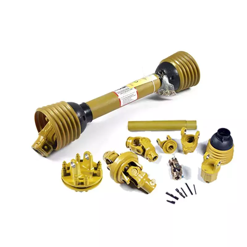 Operator awareness is key in preventing PTO shaft entanglement. It is important to avoid performing any repairs while the machine is operating. It is also important to avoid wearing loose or frayed clothing that could become entangled in the rotating shaft. It is also essential to read and follow the tractor’s operating manual. Also, ensure that the PTO shaft is only used for its intended purpose.
A power take-off, or PTO, is a type of attachment that transmits mechanical power from a tractor to another piece of farm machinery. Common examples include hay balers, rotary cutters, weed mowers, and forage blowers. These attachments are often equipped with protective shields to prevent entanglement. The shaft should always be covered when in use.
Operators should also avoid getting too close to the PTO shaft. The operator may become entangled if they accidentally approach the spinning shaft. They should also avoid wearing loose clothing because loose clothing can easily get caught in the stub and cause serious injury. These safety precautions are essential for safe operation of all farm machinery.
When using a PTO with heavy drive, it is important to use a heavy-duty model with a PTO shaft that is appropriate for the application. Alternatively, use a universal joint or wide-angle universal joint. These attachments can be a safer alternative to traditional PTOs. Draw-bar pins on trailed machines should be firmly secured to avoid damaging the PTO shaft. It is also recommended to guard all drive shafts on the machine.
Design
A PTO shaft has several advantages. It is a versatile power transmission that is ideal for heavy-duty equipment. Its design is rigid, yet flexible, allowing for high-speed operation. This is due in part to the splines, which prevent the parts from separating during operation.
The gears of a PTO drive are made from high-quality steel, which increases their durability. They are made from SCM 440 gear material. This material has a high tensile strength and a high yield point. It also has a high Young’s modulus of 206,000 N/mm2. Its Poisson’s ratio is 0.3, while its pressure angle is twenty degrees. In addition, its addendum and dedendum coefficients are both greater than 1.0.
Designed for use on industrial and marine engines, PTOs allow the driver to transfer power from a primary mover to a PTO-powered attachment. They are easy to install and offer improved service life and decreased downtime. In aircraft applications, PTOs are also common. Jet aircraft and agricultural equipment often use PTOs.
The PTO shaft’s dimensions are crucial for preventing vibration. It should extend at least 14 inches from the hitch point to the input shaft of the implement. In some cases, a shorter shaft may not fit the tractor, so it is important to choose the right size. If the PTO shaft is too short, it could cause the two parts to separate when the tractor is turning a corner.
Cost
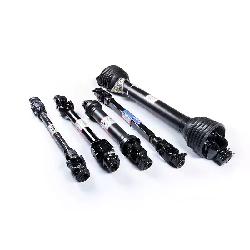 A PTO shaft is a very important part of a tractor because it transfers power to an attached attachment. These attachments typically include rotary tillers, brush cutters, hush hug, and mowers. While many attachments use a PTO shaft, the connection flange is not standardized. Some older models of tractors may have a connection flange that is closer to the tractor.
A PTO shaft will work with either a standard or a Weasler yoke. You can also choose from metric and North American models. There are also Italian PTO shafts. To ensure the best performance and durability, it is essential to ensure that the shaft is free of damage. To avoid such damage, a PTO shaft should be purchased from a reputable supplier.
PTO shafts are made from high-quality steel and feature a 1-3/8″ 6-spline at both the tractor and the implement end. In addition, splined PTO shafts are easy to replace and provide excellent horsepower. These PTO shafts can also increase a tractor’s work efficiency.
The cost of a PTO shaft replacement can vary. The average price range for a front-wheel-drive half-shaft is $470 to $940, and the cost for a rear-wheel-drive drive half-shaft replacement is about $1,600 to $2,000. The parts cost about two hundred dollars and the labor could take an hour or more.
Buying guide
If you’re looking to replace a PTO shaft on a lawn tractor, it’s important to consider several factors. First, the PTO shaft needs to be compatible with the tractor you plan to use it on. Then, you need to determine which size universal joint you need. To do this, you can use a PTO shaft size chart.
The PTO shaft is the component that transfers power from the tractor to the attached implement. It’s made up of several parts, including the internal and external PTO yoke, the universal joint, and the safety chain and shield. There are several types of PTO shafts available. You’ll want to choose the right size for your machine, as well as the number of PTO shafts you need.
A PTO shaft is essential for a tractor because without it, the tractor cannot drive. Understanding the PTO parts will help you operate farm machinery more effectively. For instance, if you’re buying a new Power Take Off shaft, you’ll want to look for one that’s compatible with the model and year of the tractor.
You’ll also need to consider the length of the PTO shaft. A PTO shaft can vary from 53 inches when compressed to 77 inches when fully extended. The most common length for a PTO shaft is about fifty-three inches, but you can also choose a longer one if you need more flexibility.

editor by czh 2022-12-20